| CPC H02M 1/4208 (2013.01) [H02M 1/143 (2013.01); H02M 3/07 (2013.01); H02M 7/04 (2013.01); H02M 7/2176 (2013.01); H02M 7/49 (2013.01)] | 35 Claims |

|
1. An alternating current (AC) to direct current (DC) conversion circuit, comprising:
a rectifier circuit, a first direct current to direct current (DC to DC) conversion module and a second DC to DC conversion module, wherein,
the rectifier circuit is configured to receive an AC input voltage, convert the AC input voltage into a DC input voltage, and output the converted DC input voltage;
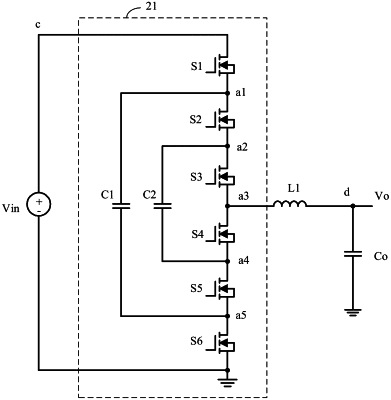
the first DC to DC conversion module comprises a plurality of power switches and an inductor, an input end of the first DC to DC conversion module is coupled to an output end of the rectifier circuit, an output end of the first DC to DC conversion module is coupled to an input end of the second DC to DC conversion module, and the first DC to DC conversion module is configured to perform power factor correction, so that a waveform of an input current of the first DC to DC conversion module corresponds to a waveform of the DC input voltage, and wherein a conductive path for receiving the DC input voltage comprises at least two power switches that are in a turn-on state, to reduce a voltage across each power switches in the first DC to DC conversion module; and
an output end of the second DC to DC conversion module is coupled to a load, and the second DC to DC conversion module is configured to convert a signal outputted by the first DC to DC conversion module into a first output signal, to drive the load, wherein the alternating current to direct current conversion circuit further comprises a first control circuit configured to determine, for each of the plurality of power switches in the first DC to DC conversion module and based on an output voltage sampling signal and an inductor current in the first DC to DC conversion module, a time instant when the power switch is turned on and a time instant when the power switch is turned off.
|