| CPC H02M 1/08 (2013.01) [H02M 1/0038 (2021.05); H02M 5/225 (2013.01); H02M 5/293 (2013.01); G05F 1/575 (2013.01); H02M 1/083 (2013.01); H02M 3/156 (2013.01)] | 24 Claims |

|
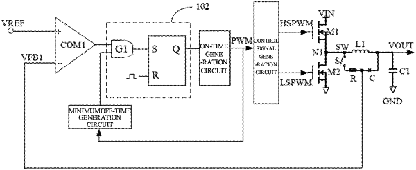
1. A control circuit for a power converter, the power converter comprising a switching transistor and an output inductor, wherein the output inductor comprises a first terminal serving as an output lode and a second terminal serving as a switching node, wherein the control circuit is configured to generate a control signal for controlling the switching transistor in the power converter, and wherein the control circuit comprises:
a resistor-capacitor (RC) oscillator network connected in parallel to the output inductor, wherein the RC oscillator network is configured to generate an oscillation signal containing a feedback ramp compensation component in response to a change in a voltage across the output inductor, wherein in case of an inductor current being in a zero-current interval and the power converter being operating in a discontinuous inductor current mode (DCM), the RC oscillator network is disconnected from the output inductor, so as to free the oscillation signal from an influence of the voltage across the output inductor;
a comparator comprising a first input, a second input and an output, wherein: the first input of the comparator is configured to receive a reference signal; the second input of the comparator is configured to receive a feedback signal; and the output of the comparator is configured to output a comparison signal, and wherein the oscillation signal is coupled into the reference signal or in the feedback signal;
an on-time generation circuit configured to start a timer based on the comparison signal or a control signal, to generate an on-time timer signal; and
a control signal generation circuit configured to generate, based on the comparison signal and the on-time timer signal, the control signal for controlling the switching transistor in the power converter.
|