| CPC H01M 10/0404 (2013.01) [B65H 35/08 (2013.01); H01M 50/406 (2021.01); B32B 38/0004 (2013.01)] | 15 Claims |

|
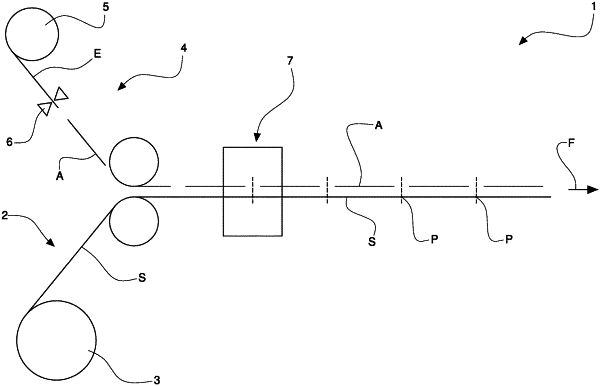
1. Method for assembling electrodes, comprising the steps of:
feeding at least one separator (S; S1, S2) in a feeding direction (F) along a feeding path;
arranging electrodes (A; C) one after the other at a mutual distance (H) on at least one side of said separator along said feeding path;
cutting said separator (S; S1, S2) along a cutting line that is transverse to said feeding direction (F) and is arranged in a separator portion (P) that is free of electrodes and is comprised between two adjacent electrodes, said cutting step being performed by means of at least one cutting device (7);
driving said separator (S; S1, S2) and said electrodes (A; C) arranged on said separator;
characterized in that:
said driving step is performed by means of two pairs of driving rollers (10) arranged one upstream and the other downstream of said cutting device (7) such that said cutting device (7) is spaced apart from and is at a different location than each pair of said two pairs of driving rollers;
said step of cutting said separator along a cutting line arranged in a separator portion (P) between two adjacent electrodes occurs at a time when said two pairs of driving rollers (10) engage said two adjacent electrodes.
|
|
7. Apparatus for assembling electrodes, in particular for implementing a method according to claim 1, said apparatus comprising:
at least one separator feeder (2) configured to feed at least one separator (S; S1, S2) in a feeding direction (F) along a feeding path;
at least one electrode feeder (4) configured to arrange electrodes (A; C) in succession one after the other at a mutual distance (H) on at least one side of the separator (S; S1, S2) along said feeding path;
at least one cutting device (7) arranged along said feeding path after said electrode feeder (4) to cut the separator (S; S1, S2) along at least one cutting line that is transverse to said feeding direction (F);
at least two pairs of driving rollers (10) arranged one immediately upstream of said cutting device (7) and the other immediately downstream of said one cutting device (7) to drive separator and electrodes along said feeding path;
wherein said cutting device (7) is spaced apart from and is at a different location than each pair of said two pairs of driving rollers (10).
|