| CPC H01J 37/32449 (2013.01) [C23C 16/45504 (2013.01); C23C 16/45589 (2013.01); H01J 37/32633 (2013.01); C23C 16/4583 (2013.01); C23C 16/45502 (2013.01); C23C 16/45591 (2013.01); H01J 37/32357 (2013.01); H01L 21/67326 (2013.01)] | 20 Claims |

|
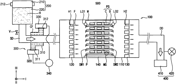
1. An apparatus for conducting a surface treatment process, comprising:
a process chamber configured that the surface treatment process is conducted to a package structure;
a plasma generator configured to generate process radicals as a plasma state for the surface treatment process, the plasma generator being positioned outside of the process chamber and connected to the process chamber by a supply duct;
a heat exchanger arranged on the supply duct and configured to cool down temperature of the process radicals passing through the supply duct;
a flow controller configured to control the process radicals to flow out of the process chamber, the flow controller being connected to a discharge duct configured that the process radicals are discharged outside the process chamber through the discharge duct;
a supply baffle including a plurality of inlet hole rows within the process chamber, each of the plurality of inlet hole rows including a plurality of inlet holes arranged in a horizontal direction;
a discharge baffle including a plurality of outlet hole rows within the process chamber, each of the plurality of outlet hole rows including a plurality of outlet holes arranged in the horizontal direction;
a first inlet hole cover configured to open and close a corresponding inlet hole row, the first inlet hole cover including a first cover driver and a first cover bar, the first cover driver configured to move the first cover bar; and
a first outlet hole cover configured to open and close a corresponding outlet hole row, the first outlet hole cover including a second cover driver and a second cover bar, the second cover driver configured to move the second cover bar,
wherein the first inlet hole cover and the first outlet hole cover are positioned at the same height and configured to be simultaneously operated to simultaneously open or close the corresponding inlet and outlet hole rows,
wherein a treatment space of the process chamber is defined between the supply baffle and the discharge baffle,
wherein each of the plurality of outlet hole rows is positioned at the same height as a corresponding one of the plurality of inlet hole rows for the process radicals to flow uniformly along a height from the supply baffle to the discharge baffle;
wherein the first inlet hole cover is positioned to cover a single inlet hole row of the plurality of inlet hole rows, and
wherein the first outlet hole cover is positioned to cover a single outlet hole row of the plurality of outlet hole rows.
|