| CPC H01H 50/56 (2013.01) [H01H 47/22 (2013.01); H01H 50/546 (2013.01)] | 8 Claims |

|
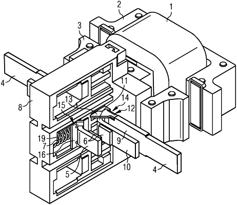
1. A low-voltage switching device comprising:
an electromagnetic drive comprising a coil, a fixedly positioned yoke and an armature that is movable in relation to the fixedly positioned yoke; and
a contact system comprising a fixedly positioned switching piece carrier and a movable switching piece carrier arranged opposite the fixedly positioned switching piece carrier, wherein the fixedly positioned switching piece carrier and the movable switching piece carrier each include contacts arranged opposite each other,
wherein the movable switching piece carrier is acted upon by a contact load spring, wherein a first electromagnetic contact load support comprising a ferromagnetic plate shaped in a U-shaped manner with two first opposing pole faces is positioned on the fixedly positioned switching piece carrier;
wherein a second electromagnetic contact load support comprising a ferromagnetic spring cup formed in a U-shaped manner with two opposing second legs is positioned between the contact load spring and the movable switching piece carrier;
wherein the two opposing second legs of the second electromagnetic contact load support and the two first opposing pole faces of the first electromagnetic contact load support are configured as directed toward one another, with an air gap between the two opposing second legs of the second electromagnetic contact load support and the two first opposing pole faces of the first electromagnetic contact load support when the contacts are open and closed.
|