| CPC G03F 7/2053 (2013.01) | 8 Claims |

|
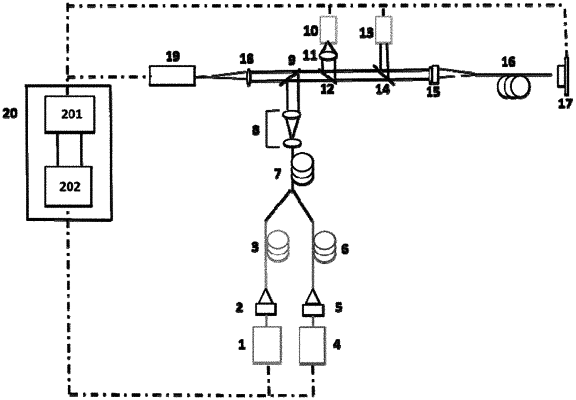
1. An integrated super-resolution laser direct-writing device, comprising
a first continuous laser (1),
a first optical fiber coupler (2),
a mono-mode optical fiber (3),
a second continuous laser (4),
a second optical fiber coupler (5),
a first annular photonic crystal fiber (6),
a bifurcated optical fiber (7),
a lens group (8),
a first dichroic mirror (9),
an LED light source (10),
a lens (11),
a second dichroic mirror (12),
an auto-focusing module (13),
a third dichroic mirror (14),
a third optical fiber coupler (15),
a square-law graded index fiber (16),
a nanometer displacement table (17),
a second lens (18),
a CMOS camera (19), and
a control system (20),
wherein an laser output by the first continuous laser (1) is input to the mono-mode optical fiber (3) through the first optical fiber coupler (2) and being used as a central inducing light;
an laser output by the second continuous laser (4) is input to the first annular photonic crystal fiber (6) through the second optical fiber coupler (5) and being used as a peripheral vortex inhibiting light;
the peripheral vortex inhibiting light and the central inducing light are combined by the bifurcated optical fiber (7) to obtain a light beam, the light beam is expanded by the lens group (8) and becomes incident to the first dichroic mirror (9), then, the light beam is reflected by the first dichroic mirror (9), sequentially transmitted by the second dichroic mirror (12) and the third dichroic mirror (14), and becomes incident to the third optical fiber coupler (15), and after sequentially passing through the third optical fiber coupler (15) and the square-law graded index fiber (16), is irradiated on a sample;
a light beam emitted by the LED light source (10) is incident to the second dichroic mirror (12) after being expanded by the lens (11), reflected by the second dichroic mirror (12), sequentially passes through the third dichroic mirror (14) and the third optical fiber coupler (15), and becomes incident to the square-law graded index fiber (16) to irradiate the sample, then, the light beam is reflected by the sample, and the reflected light beam returns along an original optical path, sequentially passing through the square-law graded index fiber (16), the third optical fiber coupler (15) and the third dichroic mirror (14), is incident to the second dichroic mirror (12), sequentially transmitted by the second dichroic mirror (12) and the first dichroic mirror (9) and becomes incident to the second lens (18), is focused by the second lens (18) and becomes incident to the CMOS camera (19) and imaged by the CMOS camera (19);
an eccentric light beam emitted by the auto-focusing module (13) enters the square-law graded index fiber (16) through the optical fiber coupler (15) to irradiate the sample after being reflected by the third dichroic mirror (14), returns along the original optical path after being reflected by the sample, becomes incident to the third dichroic mirror (14) after sequentially through the square-law graded index fiber (16) and the third optical fiber coupler (15), then becomes incident to the second lens (18) after sequentially transmitted by the third dichroic mirror (14), the second dichroic mirror (12), and the first dichroic mirror (9), becomes incident to the CMOS camera (19) after being focused by the second lens (18), and is imaged by the CMOS camera (19); and
the control system (20) is respectively connected with control ends of the first continuous laser (1), the second continuous laser (4), the LED light source (10), the auto-focusing module (13) and the nanometer displacement table (17), and the control system (20) is connected with an output end of the CMOS camera (19).
|