| CPC G01R 15/186 (2013.01) [G01R 19/0053 (2013.01)] | 20 Claims |

|
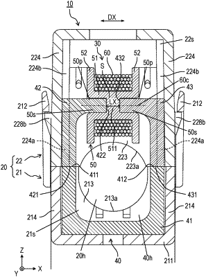
1. A current sensor configured to detect a current flowing through an electrical conductor, the current sensor comprising:
a core having a hollow configure to allow the electrical conductor to pass through the hollow; and
a coil wound around the core, wherein:
the core substantially has a C-shape having a gap connected to the hollow,
the core has a first end surface and a second end surface which face each other across the gap, the first end surface and the second end surface being directed in directions opposite to each other,
the C-shape of the core is extended continuously from the first end surface to the second end surface while surrounding the hollow, and
at least a part of the gap of the core is located inside the coil.
|