| CPC F41A 3/72 (2013.01) [F41A 35/06 (2013.01)] | 26 Claims |

|
1. A method of manufacturing a charging handle for use with a gas operated rifle, the rifle comprising an upper receiver and a bolt slidingly disposed therein, the upper receiver comprising an upper receiver wall comprising inner surfaces defining a channel and outer surfaces defining a depression, the method comprising:
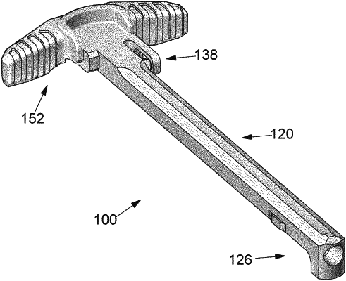
providing a body comprising a handle portion, a bolt engaging portion, and a shaft portion, the shaft portion extending in a forward direction from the handle portion to the bolt engaging portion, the shaft portion being dimensioned to extend into the channel defined by the inner surfaces of the upper receiver, the bolt engaging portion comprising a projection configured and dimensioned to engage the bolt of the rifle for pulling the bolt in the rearward direction as the charging handle is pulled rearward from a fully inserted position to a more rearward position; the handle portion comprising at least one arm extending away from the shaft portion;
providing a latch member comprising a leaf spring, a rearward portion of the latch member being fixed to the body of the charging handle, the leaf spring extending in the forward direction and comprising a foot portion dimensioned and configured to be received in the depression defined by the upper receiver wall when the charging handle is in the fully inserted position and the leaf spring configured to deflect allowing the foot portion to exit the depression when the charging handle is pulled rearward from the fully inserted position to a more rearward position;
placing at least the handle portion of the body within a cavity defined by a mold;
injecting molten thermoplastic material into the cavity defined by the mold;
allowing the thermoplastic material to cool, forming a grip portion encasing at least part of the handle portion of the body;
removing the grip portion and the handle portion from the cavity defined by the mold.
|