| CPC F28F 9/22 (2013.01) | 4 Claims |

|
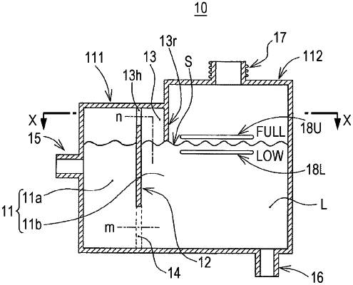
1. A reservoir tank comprising:
a tank body that stores cooling fluid;
an inflow pipe for feeding the cooling fluid into the tank body;
a discharge pipe for discharging the cooling fluid from the tank body; and
a filler port for filling the tank body with the cooling fluid, wherein
the tank body has a first chamber connected to the inflow pipe and a second chamber disposed downstream of the first chamber,
the filler port is provided to fill the second chamber with the cooling fluid,
an upper limit mark and a lower limit mark indicating an appropriate liquid level height of the cooling fluid are displayed on the tank body,
the discharge pipe is connected to the second chamber on a vertically lower side of the lower limit mark,
the first chamber and the second chamber communicate with each other through a lower communication path,
the lower communication path communicates a portion of the first chamber lower than the lower limit mark and a portion of the second chamber lower than the lower limit mark,
the first chamber and the second chamber communicate with each other through an upper communication path,
the upper communication path communicates a portion of the first chamber higher than the upper limit mark and a portion of the second chamber below the upper limit mark,
the upper communication path is defined by a tubular pipe line having openings,
the openings consist of a first opening located at one end of the pipe line and a second opening located at another end of the pipe line,
the first opening faces the first chamber at a position higher than the upper limit mark, the second opening faces the second chamber at a position below the upper limit mark, and
the reservoir tank further comprises a rib in the second chamber, the rib extending from a top inner surface of the second chamber to the position below the upper limit mark and above the lower limit mark so as to divide the tubular pipe line from the second chamber; the rib, the top inner surface of the second chamber and a partition wall dividing the first chamber and the second chamber define the tubular pipe line.
|