| CPC F23R 3/14 (2013.01) [F23R 3/002 (2013.01); F23R 3/283 (2013.01); F23R 3/286 (2013.01)] | 17 Claims |

|
1. A combustor for a gas turbine engine, the combustor comprising:
a combustion chamber defined between an inner shell and an outer shell;
a hood chamber separated from the combustion chamber by a bulkhead extending between the inner shell and the outer shell, the bulkhead comprising at least one opening extending between the hood chamber and the combustion chamber;
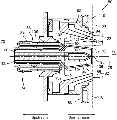
a fuel injector extending through the at least one opening, the fuel injector comprising a fuel injector body comprising a bluff body portion, the bluff body portion comprising an outer radial surface and a tip surface, the outer radial surface forming an exterior of the fuel injector, the outer radial surface extending between a first axial surface end and a second axial surface end, the outer radial surface intersecting the tip surface at the second axial surface end, the tip surface located at a downstream end of the fuel injector body, the fuel injector further comprising a primary fuel passage comprising a primary fuel outlet located in a center of the tip surface within the combustion chamber, the fuel injector further comprising a secondary fuel passage comprising a plurality of circumferentially-spaced secondary fuel passage branches, each secondary fuel passage branch including a secondary fuel outlet at the first axial surface end, each secondary fuel outlet located within the hood chamber; and
a swirler comprising a swirler body extending through the at least one opening and located radially outside of the fuel injector with respect to a fuel injector center axis, the swirler body extending axially from a first axial end to a second axial end, the first axial end axially spaced upstream of the at least one opening, the second axial end axially spaced downstream of the at least one opening, the swirler comprising a swirler exit plane defined by the second axial end of the swirler body;
wherein the tip surface extends along and is substantially parallel to the swirler exit plane from the primary fuel outlet to the outer radial surface.
|