| CPC F23G 7/08 (2013.01) [F23G 7/065 (2013.01); F05D 2240/12 (2013.01); F23G 2204/103 (2013.01); F23G 2207/101 (2013.01); F23G 2207/102 (2013.01); F23G 2207/20 (2013.01); F23G 2207/30 (2013.01); F23G 2209/14 (2013.01); F23G 2209/141 (2013.01)] | 8 Claims |

|
1. A method for controlling continuous combustion of a first gas within an enclosed combustor; the method comprising:
providing the enclosed combustor with a plurality of combustor burners, each combustor burner comprising a burner tip delivering a fuel-rich burner jet and;
monitoring a combustion zone temperature T using a sensor in electronic communication with a computer control system, the computer control system configured to receive signals from the sensor and send and receive signals to and from a first gas line valve, a second gas line valve, and an air damper regulator;
varying a flow of at least one of a first gas, a second gas, and air in response to the combustion zone temperature T by adjusting at least one of the first gas line valve, the second gas line valve, and the air damper regulator, thereby aiding combustion of the first gas;
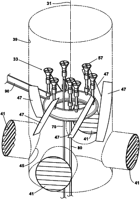
swirling the first gas, the second gas, or a mixture of the first and second gases within the enclosed combustor with gas swirling vanes in the form of flat plates that are arranged about a central longitudinal axis of each burner tip of the plurality of combustor burners of in the enclosed combustor; and
swirling the air within the enclosed combustor with air swirling vanes in the form of inclined wall vanes located on the enclosed combustor sidewalls above the air damper regulator and below the uppermost end of each burner tip of the plurality of combustor burners;
wherein the first gas has a varying combustibility and the second gas has a higher heating value than the first gas;
wherein a pilot gas line is configured to permit a pilot gas flow along the pilot gas line to the enclosed combustor, the pilot gas line being independent of the first and second gas lines;
wherein the computer control system is further configured to shut down the first gas line valve, the second gas line valve, and a valve to the pilot gas line when the combustion zone temperature T surpasses a safety limit.
|