| CPC F16D 55/225 (2013.01) [F16D 65/005 (2013.01); F16D 65/097 (2013.01); F16D 2055/0004 (2013.01); F16D 2055/0075 (2013.01); F16D 2127/02 (2013.01)] | 8 Claims |

|
1. A brake assembly comprising:
a brake carrier;
a caliper that is mounted to the brake carrier;
a first brake pad that is received in the brake carrier, the first brake pad having a first backplate and a first friction material;
a second brake pad that is received in the brake carrier, the second brake pad having a second backplate and a second friction material;
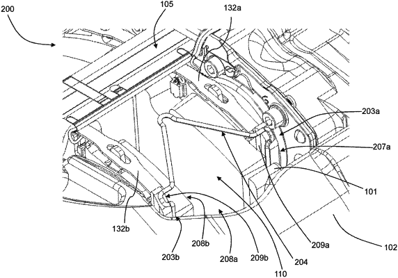
a pad retraction spring having a first supporting portion, a first engaging portion and a second engaging portion; and
a first stop surface;
wherein the first friction material and the second friction material face each other and define a partially enclosed volume therebetween for accommodating a brake rotor, the first stop surface located radially outward of the partially enclosed volume, wherein a rotor plane is disposed between the first brake pad and the second brake pad;
wherein the first backplate comprises a first backplate face and the second backplate comprises a second backplate face, the first and second backplate faces facing the rotor plane;
wherein the first engaging portion of the pad retraction spring engages the first backplate face and the second engaging portion of the pad retraction spring engages the second backplate face, the pad retraction spring urging the first and second brake pads in a direction away from the rotor plane, wherein the first supporting portion is configured to abut the first stop surface such that the pad retraction spring is inhibited from entering the partially enclosed volume;
wherein the first backplate comprises a first circumferential end surface and a first backplate radially outer surface, the first backplate radially outer surface joined to the first circumferential end surface at a corner region, wherein the first backplate radially outer surface comprises the first stop surface;
wherein the first backplate face comprises a first circumferential end region where the first friction material is recessed and the second backplate face comprises a second circumferential end region where the second friction material is recessed, wherein the first engaging portion engages the first circumferential end region and the second engaging portion engages the second circumferential end region; and
wherein the first circumferential end region extends from a first radially outer edge to a first radially inner edge of the first backplate face, and the second circumferential end region extends from a second radially outer edge to a second radially inner edge of the second backplate face, and the first engaging portion engages a majority of the first circumferential end region and the second engaging portion engages a majority of the second circumferential end region.
|