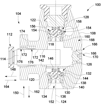
| CPC F04B 53/168 (2013.01) [F04B 1/053 (2013.01); F04B 19/22 (2013.01)] | 20 Claims |

|
5. A fluid cylinder for a fluid end section of a reciprocating pump, comprising:
a body having a pressure chamber and a plunger bore that fluidly communicates with the pressure chamber, the plunger bore comprising a packing segment configured to hold packing,
wherein the plunger bore includes a groove in an inner wall of the body;
a sleeve received within the packing segment of the plunger bore, the sleeve being configured to hold a plunger within an internal passage of the sleeve such that the plunger is configured to reciprocate within the plunger bore during operation of the reciprocating pump;
a seal between an outer wall of the sleeve and the inner wall of the body, wherein the seal is positioned relatively closer to an innermost longitudinal end of the sleeve, that faces the pressure chamber, than an outermost longitudinal end of the sleeve, that faces away from the pressure chamber; and
a snap ring secured within the plunger bore such that the snap ring is configured to retain the sleeve within the packing segment of the plunger bore,
wherein the snap ring includes a body having a ring shape,
wherein the body of the snap ring is separate from the sleeve and abuts the outermost longitudinal end of the sleeve that faces away from the pressure chamber, wherein an inner diameter of the body of the snap ring is smaller than a minimum inner diameter of the sleeve at the outermost longitudinal end, and
wherein the body of the snap ring is at least partly disposed in the groove and at least partly extending radially inward into the plunger bore.
|