| CPC F02M 31/16 (2013.01) [B01D 35/005 (2013.01); B01D 35/18 (2013.01); F01P 7/14 (2013.01); F02M 31/125 (2013.01); F02M 37/0023 (2013.01); F02M 37/0035 (2013.01); F02M 37/0052 (2013.01); F02M 37/30 (2019.01); F02M 37/32 (2019.01); Y02T 10/12 (2013.01)] | 17 Claims |

|
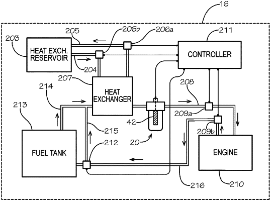
1. A method of improving fuel efficiency in vehicle, comprising the steps of:
providing a combustion system including a fuel tank, an engine, and a fuel line disposed between the fuel tank and the engine;
providing a heat exchanger on the fuel line between the fuel tank and the engine, wherein the heat exchanger includes a heat exchanger supply coupling, a heat exchanger return coupling, a first fuel line connector, and a second fuel line connector;
providing a heat exchanger reservoir on the vehicle, wherein the fuel line includes a fuel supply line upstream of the heat exchanger and a heated fuel line downstream of the heat exchanger;
connecting the first fuel line connector to the fuel supply line on the fuel line upstream of the heat exchanger;
passing fuel from the fuel supply line to the heat exchanger via the first fuel line connector;
connecting the second fuel line connector to the heated fuel line on the fuel line downstream of the heat exchanger;
passing fuel out of the heat exchanger to the heated fuel line via the second fuel line connector;
simultaneously passing working thermal fluid from the heat exchanger reservoir into the heat exchanger at a first flow rate via the heat exchanger supply coupling, through the heat exchanger, and returning the working thermal fluid from the heat exchanger to the heat exchanger reservoir via the heat exchanger return coupling such that the working thermal fluid transfers heat to the fuel inside the heat exchanger prior to delivery of the fuel to the engine for combustion, wherein the working thermal fluid does not contact the fuel inside the heat exchanger;
increasing the temperature of the fuel passing through the heat exchanger, wherein the fuel is heated in the heat exchanger;
monitoring the temperature of the heated fuel using a temperature sensor, wherein the temperature sensor includes a thermocouple attached to a support rod;
updating, via a flow controller, the simultaneous passage of working thermal fluid from the heat exchange reservoir into the heat exchanger to occur at a second flow rate different than the first flow rate based on the monitored temperature of the heated fuel;
providing a first vibration isolation mount installed between the heat exchanger and the vehicle;
reducing vibration of the heat exchanger via the first vibration isolation mount;
delivering the heated fuel from the heat exchanger to the engine; and
improving the fuel efficiency of the engine by burning the heated fuel.
|