| CPC F01D 25/285 (2013.01) [F05D 2230/68 (2013.01); F05D 2230/70 (2013.01)] | 14 Claims |

|
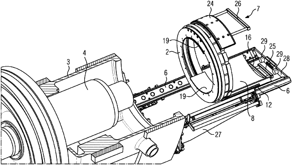
1. A device for removing and/or installing an annular component which is arranged within a turbine housing at a position which is accessible via an access point of the turbine housing, comprising:
two sliding rails configured to extend through the access point into an interior of the turbine housing when mounted to a lower turbine housing region of the turbine housing such that they extend in a longitudinal direction and parallel to one another,
a slide configured to be placed onto the sliding rails and to be slid to and fro on the sliding rails in the longitudinal direction, wherein the slide comprises a base plate and a component mount which, as viewed in the longitudinal direction, is fastened in a front end region of the base plate and is designed in such a way that the component to be removed or to be installed can be received on it and can be fastened to it releasably, the base plate being adapted to the component mount in such a way that a weight of the component which is received on the component mount is compensated for by way of a weight of the base plate as a counterweight, in such a way that wobbling of the slide on the sliding rails due to the weight of the component is prevented, wherein the slide is configured such that movement to and fro on the sliding rails is effective to move the component mount and the base plate into and out of the interior of the turbine housing,
wherein the front end region of the base plate can be moved in the longitudinal direction beyond a front end of the sliding rails, and a first sliding face is provided in a predefined region of the front end region on an underside of the base plate, and
wherein the first sliding face is disposed on a radially outer face of a sliding face element which is received in a cutout of the base plate, wherein a radially inner face of the sliding face element comprises a ramped surface that is ramped in the longitudinal direction, and wherein the sliding face element is moveable up and down relative to the base plate by moving in the longitudinal direction an adjusting unit that is disposed between the ramped surface and the base plate along the ramped surface.
|