| CPC F01D 5/282 (2013.01) [F01D 5/147 (2013.01); F01D 5/18 (2013.01); F05D 2200/11 (2013.01); F05D 2240/301 (2013.01); F05D 2240/304 (2013.01); F05D 2250/75 (2013.01); F05D 2300/6033 (2013.01); F05D 2300/6034 (2013.01)] | 14 Claims |

|
1. An airfoil comprising:
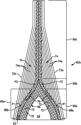
an airfoil wall defining a leading end, a trailing end, and pressure and suction sides that join the leading end and the trailing end, the airfoil wall including a wishbone-shaped fiber layer structure, the wishbone-shaped fiber layer structure including a pair of arms that merge into a single leg, the pair of arms being formed by first and second S-shaped fiber layers each of which is comprised of a network of fiber tows and each of which defines two inflection points, the first and second S-shaped fiber layers merging to form the single leg, wherein in the single leg at least one of the fiber tows from the first S-shaped fiber layer is interlaced with at least one of the fiber tows from the second S-shaped fiber layer, the single leg forming at least a portion of the trailing end of the airfoil wall.
|