| CPC B62D 33/033 (2013.01) [B62D 33/0273 (2013.01); B60P 3/40 (2013.01)] | 4 Claims |
|
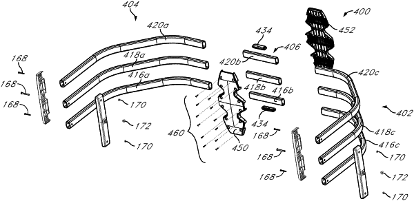
1. A vehicle tailgate enclosure for use with a vehicle including a first sidewall, a second sidewall, a cargo bed, and a tailgate, the vehicle tailgate enclosure comprising:
a first upright configured to be secured to the first sidewall of the vehicle;
a second upright configured to be secured to the second sidewall of the vehicle;
a plurality of cross-members extending between the first and second uprights over at least a portion of the tailgate of the vehicle when the vehicle tailgate enclosure is in use, each of the plurality of cross-members vertically spaced apart from an adjacent one of the plurality of cross-members, each of the plurality of cross-members comprising:
a first beam connected to the first upright;
a second beam connected to the second upright; and
a central beam connected to the first and second beams; and
a third upright positioned along the plurality of cross-members between the first and second uprights, the third upright comprising:
a first portion comprising a first channel that receives a portion of the central beam of a first one of the plurality of cross-members, the first portion having a first width;
a second portion comprising a second channel that receives a portion of the central beam of a second one of the plurality of cross-members, the second portion having a second width; and
a third portion comprising a third channel that receives a portion of the central beam of a third one of the plurality of cross-members, the third portion having a third width;
wherein the first and third widths are different than the second width; and
wherein:
the first channel receives a portion of each of the first and second beams of the first one of the plurality of cross-members;
the second channel receives a portion of each of the first and second beams of the second one of the plurality of cross-members; and
the third channel receives a portion of each of the first and second beams of the third one of the plurality of cross-members.
|