| CPC B60C 11/01 (2013.01) [B60C 11/005 (2013.01); B60C 2011/0025 (2013.01); B60C 2013/006 (2013.01); B60C 2200/06 (2013.01)] | 15 Claims |
|
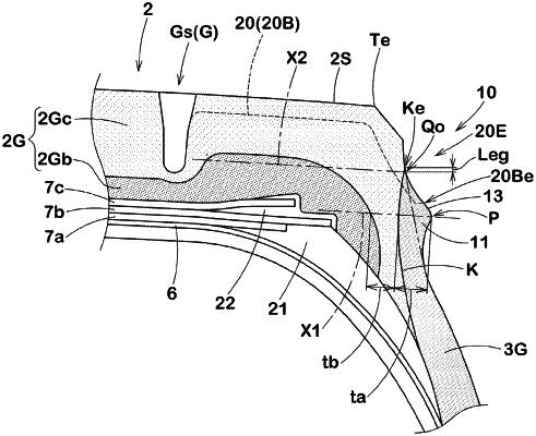
1. A heavy duty pneumatic tire comprising a tread portion having a tread surface and a sidewall portion connected to the tread surface through a buttress region, wherein
the buttress region is provided with a protruding portion protruding outwardly in a tire axial direction and extending in a tire circumferential direction,
in a tire meridian cross-sectional view, a maximum protrusion height (hmax) of the protruding portion, with respect to an imaginary buttress surface in which outer surfaces other than the protruding portion in the buttress region are smoothly connected, is equal to or more than 3.0 mm and is in a range of 0.025 to 0.050 times a tread half width (Wt),
a cross-sectional area (Sa) of the protruding portion from the imaginary buttress surface is equal to or more than 20 mm2,
the protruding portion has a triangular cross-sectional shape comprising a top portion defining the maximum protrusion height (hmax), a radially inner inclined surface and a radially outer inclined surface each of which extends to the imaginary buttress surface from the top portion while decreasing its protrusion height,
the tread portion is provided with a circumferential main groove extending in the tire circumferential direction with a groove depth (D), and at least one shoulder lateral groove having axially an outer end opening at the buttress region,
the at least one shoulder lateral groove comprises a first groove bottom extending in parallel with a tread surface, and a second groove bottom extending inwardly in a tire radial direction from the first groove bottom to the outer end opening at the buttress region,
a groove depth of the first groove bottom is smaller than the groove depth (D) of the circumferential main groove, and
the outer end of the at least one shoulder lateral groove is located on the outer inclined surface of the protruding portion.
|