| CPC B41J 13/0036 (2013.01) [B41J 13/02 (2013.01); B41J 13/106 (2013.01); B41J 29/38 (2013.01); B65H 31/02 (2013.01); B65H 2403/40 (2013.01)] | 10 Claims |

|
1. A recording device, comprising:
a recording unit that is configured to perform recording on a medium;
a discharge roller that is configured to discharge the medium on which recording was performed by the recording unit;
a medium receiving tray that is configured to receive the medium discharged by the discharge roller and switch between a first state and a second state in which the medium receiving tray is displaced in a discharge direction of the medium with respect to the first state;
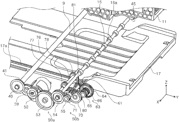
a motor that serves as a power source of the discharge roller and the medium receiving tray;
a power transmission unit that is configured to switch between a power transmission state in which power of the motor is transmitted from the motor to the medium receiving tray, and a power non-transmission state in which the power of the motor is not transmitted from the motor to the medium receiving tray; and
a restriction unit that is configured to switch between a restriction state in which the restriction unit restricts displacement of the medium receiving tray when the power transmission unit is in the power non-transmission state, and a non-restriction state in which the restriction unit does not restrict the displacement of the medium receiving tray when the power transmission unit is in the power transmission state, wherein
the power transmission unit includes a first power transmission path that is coupled to the motor, and a second power transmission path that is provided at a downstream of the first power transmission path in a transmission direction of power from the motor to the medium receiving tray,
the first power transmission path is coupled to the second power transmission path, when the power transmission unit is in the power transmission state, and the first power transmission path is uncoupled from the second power transmission path when the power transmission unit is in the power non-transmission state,
the restriction unit includes a movable member that is configured to be displaced into a contact position in which the movable member is in contact with a rotating body that is provided on the second power transmission path, and a separation position in which the movable member is separated from the rotating body, and
the movable member is located in the contact position when the restriction unit is in the restriction state, and the movable member is located in the separation position when the restriction unit is in the non-restriction state.
|