| CPC A61M 60/148 (2021.01) [A61M 60/178 (2021.01); A61M 60/216 (2021.01); A61M 60/416 (2021.01); A61M 60/419 (2021.01); A61M 60/422 (2021.01); A61M 60/585 (2021.01); A61M 60/824 (2021.01); A61M 60/857 (2021.01); A61M 60/873 (2021.01); A61M 60/876 (2021.01); A61M 60/88 (2021.01)] | 17 Claims |
|
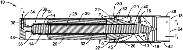
1. A heart assist device, comprising:
a rotor;
said rotor comprising a shaft with an outer surface and an impeller extending from the shaft at a first location on the outer surface of said rotor;
said outer surface comprising an outer bearing surface at a second location on the shaft;
wherein said first location and said second location on said rotor are toward opposite ends of said rotor;
a pump housing comprising a first end and a second end;
the pump housing comprising one or more cylindrical bores configured to define a pumping chamber as an interior of a first cylindrical bore having the impeller, and an inner bearing surface within a second cylindrical bore of the pump housing;
wherein said pump housing comprises a first housing section which contains the pumping chamber toward said first end of said pump housing, and which overlaps a second housing section which has a smaller diameter than said first housing section, and which is toward said second end of said pump housing;
wherein an annular outlet is disposed circumferentially between an overlap of an interior of said first housing section over an exterior of said second housing section;
wherein, in an operating configuration, the rotor is positioned within the one or more cylindrical bores such that the impeller rotates within the pumping chamber upon actuation of the rotor;
wherein said inner bearing surface of the pump housing is sufficiently closely fitted to said outer bearing surface of said shaft to form a hydrodynamic bearing clearance there between such that during actuation of the rotor the inner bearing surface of the second cylindrical bore and outer bearing surface of the shaft form a hydrodynamic journal bearing;
wherein said hydrodynamic bearing clearance comprises an annular gap formed between the inner bearing surface of the pump and said outer bearing surface of said shaft;
wherein said hydrodynamic bearing clearance encompasses a hemispherical bearing interface between a hemispherical bearing at the end of said rotor which is opposite from said impeller, and the pump housing forming a hemispherical leakage path in fluid communication with the annular gap, and in which a leakage outlet connects to the hemispherical leakage path at the base of the hemispherical bearing;
the pump housing comprising an axial inlet at the first end of the pumping chamber of the pump housing, with the axial inlet in fluid communication with the pumping chamber, with said annular outlet being located circumferentially in a middle region of the pump housing between the first and second ends of the pump housing;
wherein the leakage outlet of said pump housing is in fluid communication with the hydrodynamic bearing clearance which is also configured as a leakage flow path;
wherein said rotor is configured with a rotor magnet whereby said rotor is magnetically driven into rotation by a motor stator;
wherein rotation of the impeller on said rotor is configured for drawing the flow of blood through the axial inlet into the pumping chamber, and a first portion of this flow of blood into the leakage flow path;
wherein the first portion of the blood is directed along the length of the second bore of the hydrodynamic bearing clearance through said leakage flow path and out said leakage outlet on a circumference of the second end of the pump housing; and
wherein a second portion of blood is directed from said pumping chamber and out the annular outlet on the outer circumference on the middle region of the pump housing.
|