| CPC A61M 39/288 (2013.01) [A61M 39/284 (2013.01)] | 9 Claims |

|
1. A pinch clamp device, comprising:
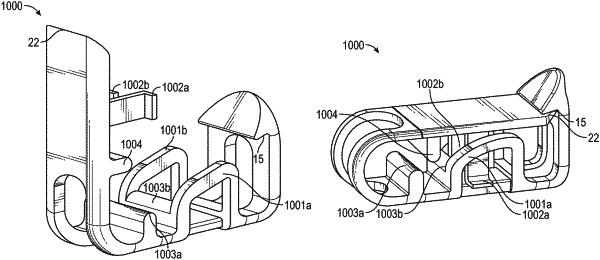
a first arm, comprising a first end, a second end, a first opening, a second opening, a first retaining component, and a second retaining component opposite the first retaining component, wherein the first retaining component and the second retaining component are disposed between the first end of the first arm and the first arm of a second arm, wherein the first retaining component forms the first opening and the second retaining component forms the second opening;
the second arm, comprising a first end, a second end, a first pivoting tab, and a second pivoting tab opposite the first pivoting tab, wherein the first pivoting tab and the second pivoting tab are disposed between the first end of the second arm and the second end of the second arm, wherein the first pivoting tab comprises a first outwardly extending tip, wherein the second pivoting tab comprises a second outwardly extending tip; and
a hinge interconnecting the second end of the first arm and the second end of the second arm,
wherein the pinch clamp device is configured to move from a first position to a second position and from the second position to a third position, wherein the first pivoting tab and the second pivoting tab bypass the first retaining component and the second retaining component, respectively, when the pinch clamp device is moved from the first position to the second position, wherein when the pinch clamp device is in the second position, the first outwardly extending tip and the second outwardly extending tip contact the first retaining component and the second retaining component, respectively, and are disposed within the first opening and the second opening, respectively, wherein when the pinch clamp device is in the third position, the first outwardly extending tip and the second outwardly extending tip are disposed within the first opening and the second opening, respectively, and are spaced apart from the first retaining component and the second retaining component, respectively,
wherein the first end of the second arm comprises an interface surface and the first end of the first arm comprises a ledge, wherein the interface surface is configured to insert under the ledge in response to moving the pinch clamp device from the second position to the third position.
|