| CPC A61C 8/0087 (2013.01) | 12 Claims |

|
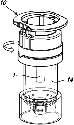
1. A receptacle for a dental implant including an implant extension, said receptacle comprising:
a cover which is formed along a longitudinal axis, the cover including a first end section which is open to an outside in a direction of the longitudinal axis and a second end section which is closed to the outside, wherein the cover surrounds an interior space which is open to the first end section and in which a holder is arranged along the longitudinal axis, the holder including a channel which is open to the outside along the longitudinal axis, the channel being formed to partially receive and to hold the implant extension during transport; and
a bottom receptacle formed tubularly along the longitudinal axis, the bottom receptacle including an outer third end section and an opposing fourth end section, the third end section being sealed tightly to the outside, the fourth end section of the bottom receptacle and the first end section of the cover being interconnectable and manually detachable to form a substantially gas and liquid tight space therebetween;
wherein:
at least three spring arms are formed and arranged in the interior space surrounded by the cover towards the longitudinal axis in such a way that the at least three spring arms are each connected to the cover at an outer first end along an annular region around the longitudinal axis and are equally spaced and resilient radially towards the longitudinal axis with a respective opposing second end,
each respective opposing second end towards the longitudinal axis includes a nub formed to engage a groove formed annularly on the implant extension when the implant extension is in a final position;
the at least three spring arms are designed geometrically and so flexible that each nub is configured to:
be pushed away from the longitudinal axis during insertion of the implant extension, and
in the final position, push into the groove with a clamping force perpendicular to the longitudinal axis;
the holder is formed as a bushing separate from the cover;
the bushing includes a plug connection towards the cover; and
the plug connection can be pushed into the cover along the longitudinal axis to thereby form a rotationally fixed connection.
|