US 11,723,646 B2
Self-drilling all-suture anchor
Grady Breslich, Bradenton, FL (US); James Barber, Largo, FL (US); Adrian Bosworth, Bradenton, FL (US); Bennie W. Gladdish, Jr., Odessa, FL (US); Peter Miller, Largo, FL (US); and John K. Sieh, Safety Harbor, FL (US)
Assigned to CONMED CORPORATION, Utica, NY (US)
Appl. No. 16/634,306
Filed by CONMED CORPORATION, Utica, NY (US)
PCT Filed Jul. 24, 2018, PCT No. PCT/US2018/043446
§ 371(c)(1), (2) Date Jan. 27, 2020,
PCT Pub. No. WO2019/023205, PCT Pub. Date Jan. 31, 2019.
Claims priority of provisional application 62/631,034, filed on Feb. 15, 2018.
Claims priority of provisional application 62/618,851, filed on Jan. 18, 2018.
Claims priority of provisional application 62/572,369, filed on Oct. 13, 2017.
Claims priority of provisional application 62/543,516, filed on Aug. 10, 2017.
Claims priority of provisional application 62/536,208, filed on Jul. 24, 2017.
Prior Publication US 2020/0360008 A1, Nov. 19, 2020
Int. Cl. A61B 17/04 (2006.01); A61B 17/17 (2006.01)
CPC A61B 17/0401 (2013.01) [A61B 17/17 (2013.01); A61B 2017/0409 (2013.01); A61B 2017/0414 (2013.01); A61B 2017/0496 (2013.01)] 21 Claims
OG exemplary drawing
 
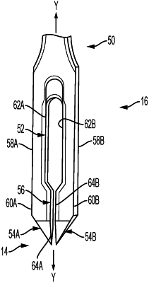
1. An anchor inserter, comprising:
a shaft extending along a longitudinal axis having a proximal end and a distal end;
an inserter tip attached to and extending distally from the shaft;
a suture anchor retention slot extending through the inserter tip, the suture anchor retention slot having a pair of opposing inner walls; and
a drilling point at a distal end of the inserter tip, and
an anchor deployment passage extending from the suture anchor retention slot to an exterior distal surface of the inserter tip, the anchor deployment passage having:
a pair of opposing drill faces,
wherein the opposing drill faces are spaced closer together than the opposing inner walls of the suture anchor retention slot.