| CPC A44B 11/223 (2013.01) [A41F 9/002 (2013.01); A41F 9/025 (2013.01); A63B 71/12 (2013.01); A63B 2244/09 (2013.01)] | 8 Claims |

|
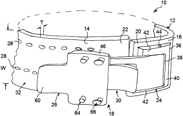
1. A weight lifting support belt comprising:
an elongate belt having a live end region and a dead end region, wherein said elongated belt defines an outwardly facing side and an inwardly facing side opposite the outwardly facing side, wherein the inwardly facing side faces the user when the weight lifting support belt is worn; and
buckling to releasably connect and secure said live end region to said dead end region,
wherein said buckling comprises a first anchor portion fixed to said live end region, a second anchor portion configured to releasably engage apertures provided in said dead end region to connect said live end region and said dead end region in a relaxed tightness condition of the support belt, a locking mechanism operable to cause a reduction in a spacing between said first anchor portion and said second anchor portion to change a tightness condition of the support belt from said relaxed tightness condition to a tightened closed condition in which a free end of said live end region overlies a free end of said dead end region, a first pivot pin pivotally connecting said first anchor portion to said locking mechanism and a second pivot pin pivotally connecting said second anchor portion to said locking mechanism,
wherein said apertures provided in said dead end region of said belt are arranged to form at least one row apertures disposed in spaced apart relation along said dead end region to define a plurality of progressively tighter second anchor engagement positions,
wherein said locking mechanism comprises a connecting arm and a separate lever arm pivotally connected to said connecting arm by a third pivot pin and operable to generate a pulling force to cause said reduction in said spacing between said first and second anchor portions, whereby a wearer can progressively tighten the belt through progressively tighter tightened closed conditions without detaching the first anchor portion from the live end region of the belt by operating said locking mechanism to change the tightness condition of the support belt from said tightened closed condition to said relaxed tightness condition, disengaging said second anchor portion from said at least one row of apertures and re-engaging said second anchor portion with said at least one row of apertures in a tighter one of said progressively tighter second anchor engagement positions and operating said locking mechanism to change the tightness condition of the support belt from said relaxed tightness condition to said tightened closed condition, and
wherein said first anchor portion is disposed against the outwardly facing side of said elongate belt and further comprising a fixing plate disposed opposite said first anchor portion against the inwardly facing side of said elongate belt, said fixing plate defining a recess and said second anchor portion comprising a tongue configured to slide into said recess during tightening of said buckling.
|