| CPC H04L 49/253 (2013.01) [H04L 47/2483 (2013.01); H04L 49/10 (2013.01); H04L 49/354 (2013.01); H04L 12/4633 (2013.01)] | 16 Claims |

|
8. A stack having at least two switches for transmitting network traffic through the stack, each switch comprising:
a memory configured to store instructions;
processor disposed in communication with said memory, wherein the processor associated with a switch of the at least two switches upon execution of the instructions is configured to:
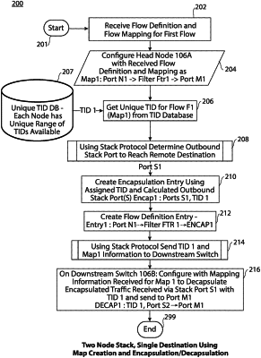
configure a switch of the at least two switches with mapping information based on a user input flow definition and flow mapping for a flow, wherein the flow definition includes user configurable rules to identify the flow, wherein the flow mapping defines one or more destination ports having one or more local destination ports and/or one or more remote destination ports for the flow to exit the stack, and wherein the mapping information includes the one or more local destination ports, via which the flow can exit the stack from the switch, and an outbound stack port for each of the one or more remote destination ports, via which the flow can be transmitted from the switch to a downstream switch;
create a decapsulation entry that corresponds to the flow, the decapsulation entry having an associated flow identification (ID) for the flow, wherein the flow ID is assigned to the flow and is unique across the stack;
configure the switch with access to a decapsulation algorithm, the decapsulation algorithm being configured to use the flow ID via the decapsulation entry to decapsulate encapsulated network traffic of the flow received from an upstream switch of the at least two switches, wherein the at least two switches further include at least one downstream switch that is downstream from the switch,
create an encapsulation entry that corresponds to the flow, the encapsulation entry having the flow ID for the flow and configure the switch with access to an encapsulation algorithm, the encapsulation algorithm being configured to use the flow ID via the encapsulation entry to encapsulate the decapsulated network traffic of the flow prior to the switch transmitting the encapsulated network traffic to the at least one downstream switch; and
store the flow definition and the flow mapping in a high-speed memory, wherein the second encapsulation entry, the flow definition, and the flow mapping are stored in association with one another, and wherein the mapping information further includes one or more second local destination ports that are local to the second switch.
|