| CPC H04L 45/54 (2013.01) [H04L 12/4641 (2013.01); H04L 45/586 (2013.01); H04L 45/745 (2013.01)] | 4 Claims |

|
1. A virtual network controller comprising one or more processors implemented in circuitry and configured to:
configure a first network switch of an interconnected switch fabric to apply a first virtual routing and forwarding (VRF) table to network traffic flowing to and from a first set of server devices of a data center, the first set of server devices being associated with a first tenant of the data center, wherein the first network switch is communicatively coupled to the first set of server devices;
configure the first network switch to apply a first logical router VRF table to network traffic flowing to and from one or more bridge domains associated with the first tenant, wherein the first logical router VRF table is separate from the first VRF table;
configure a second network switch of the interconnected switch fabric to apply a second VRF table to network traffic flowing to and from a second set of server devices of the data center, the second set of server devices being associated with a second tenant of the data center, wherein the second network switch is communicatively coupled to the second set of server devices; and
configure the second network switch to apply a second logical router VRF table to network traffic flowing to and from one or more bridge domains associated with the second tenant, wherein the second logical router VRF table is separate from the second VRF table;
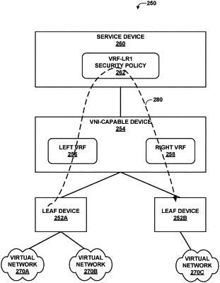
configure a third network switch communicatively coupled between the first network switch and the second network switch to include a set of service VRF tables, separate from the first and second logical router VRF tables, for diverting the network traffic to a set of one or more service units for application of at least one service, wherein the set of service VRF tables includes a first service VRF table for forwarding inter-tenant network traffic through the one or more service units in a direction from the first network switch to the second network switch, and a second service VRF table for forwarding inter-tenant network traffic through the one or more service units in a direction from the second network switch to the first network switch.
|