| CPC H03L 7/093 (2013.01) [H03L 7/0893 (2013.01); H03L 7/091 (2013.01); H03L 7/0992 (2013.01)] | 21 Claims |

|
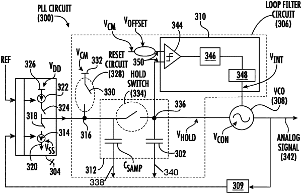
1. A phase-locked loop (PLL) circuit comprising:
a voltage controlled oscillator (VCO) circuit configured to generate an analog signal, wherein a frequency of the analog signal is based on a first control voltage and a second control voltage;
a charge pump circuit; and
a loop filter comprising:
a first sample capacitor comprising a first sample node coupled to the charge pump circuit;
a reset circuit coupled to the sample node;
a first hold capacitor comprising a first hold node, wherein the first control voltage comprises a voltage on the first hold node;
a hold switch coupled to the first sample node and the first hold node; and
an integral component circuit comprising:
a comparator coupled to the first hold node; and
a digital accumulator coupled to a comparator output of the comparator;
wherein the second control voltage is generated based on accumulated states of the first control voltage.
|