| CPC H03H 7/463 (2013.01) [H03H 7/0115 (2013.01); H03H 7/175 (2013.01); H03H 7/1775 (2013.01)] | 13 Claims |

|
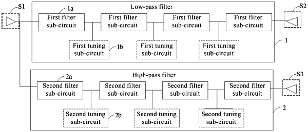
1. A radio frequency duplexer circuit, comprising:
a first terminal configured to receive an input signal;
a second terminal configured to output a low frequency signal;
a third terminal configured to output a high frequency signal;
a first band-pass filter coupled between the first terminal and the second terminal; and
a second band-pass filter coupled between the first terminal and the third terminal, wherein
the first band-pass filter comprises N first filter sub-circuits coupled in series and a first tuning sub-circuit coupled to at least a portion of the N first filter sub-circuits, each of the N first filter sub-circuits comprises a first end and a second end, and the second end of a 1st first filter sub-circuit is coupled to the first tuning sub-circuit;
among the N first filter sub-circuits coupled in series, a first end of the 1st first filter sub-circuit is coupled to the first terminal, and a second end of a Nth first filter sub-circuit is coupled to the second terminal; N is an integer greater than or equal to 1; each of the N first filter sub-circuits is configured to filter out a high frequency signal; and the first tuning sub-circuit is configured to pass a high frequency signal therethrough;
the second band-pass filter comprises M second filter sub-circuits coupled in series and a second tuning sub-circuit coupled to at least a portion of the M second filter sub-circuits; each of the M second filter sub-circuits comprises a first end and a second end, and the second end of a 1st second filter sub-circuit is coupled to the second tuning sub-circuit;
among the M second filter sub-circuits coupled in series, a first end of the 1st second filter sub-circuit is coupled to the first terminal, and a second end of a Mth second filter sub-circuit is coupled to the third terminal; M is an integer greater than or equal to 1; each of the M second filter sub-circuits is configured to filter out a low frequency signal; the second tuning sub-circuit is configured to pass a low frequency signal therethrough,
each of the N first filter sub-circuits coupled in series comprises a first inductor and a first capacitor coupled in series; the first inductors and the first capacitors of the N first filter sub-circuits coupled in series are sequentially coupled in series, a first end of a first inductor of the 1st first filter sub-circuit is coupled to the first terminal, and a first capacitor of the Nth first filter sub-circuit is coupled to the second terminal, wherein a first end of a first inductor of an ith one of the N first filter sub-circuits coupled in series is coupled to a second end of a first capacitor of an (i−1)th first filter sub-circuit, a second end of a first capacitor of the ith first filter sub-circuit is coupled to a first end of a first inductor of an (i+1)th first filter sub-circuit, i<N,
the first tuning sub-circuit comprises a second inductor and a second capacitor coupled in parallel; wherein
a first end of the second inductor is directly coupled to a first end of the second capacitor, and the first end of the second inductor and the first end of the second capacitor are directly coupled between two directly adjacent first filter sub-circuits, and
a second end of the second inductor is directly coupled to a second end of the second capacitor, and the second end of the second inductor and the second end of the second capacitor are directly coupled to a grounding terminal,
the first end of the second inductor and the first end of the second capacitor are directly and commonly coupled to the first end of the first inductor of the ith first filter sub-circuit and the second end of the first capacitor of the (i−1)th first filter sub-circuit of the N first filter sub-circuits coupled in series.
|