| CPC H02P 27/085 (2013.01) [H02M 1/0043 (2021.05); H02M 7/5395 (2013.01); H02K 7/006 (2013.01)] | 9 Claims |

|
7. An electric vehicle comprising:
a vehicle body;
a high voltage direct current (DC) electrical battery disposed within the vehicle body;
left and right front wheels configured to rotate;
left and right rear wheels configured to rotate;
left and right electric motors mechanically couplable to rotate at least one set of wheels chosen from the left and right front wheels and the left and right rear wheels; and
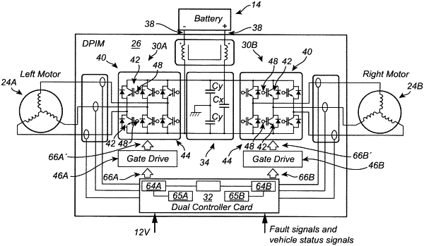
at least one dual power inverter module including:
a DC link capacitor electrically connectable to the high voltage DC electrical battery;
a first power inverter electrically connectable to the DC link capacitor and configured to convert high voltage DC electrical power to three phase high voltage alternating current (AC) electrical power, the first power inverter being further configured to supply the three phase high voltage AC electrical power to an electric motor chosen from the left and right electric motors;
a second power inverter electrically connectable to the DC link capacitor and configured to convert high voltage DC electrical power to three phase high voltage AC electrical power, the second power inverter being further configured to supply the three phase high voltage AC electrical power to the other electric motor chosen from the left and right electric motors; and
a common controller electrically connectable to the first power inverter and the second power inverter, the common controller being configured to control the first power inverter and the second power inverter, the common controller including:
a first processor for the first power inverter;
a non-transitory computer-readable medium configured to store computer-executable instructions configured to cause the first processor to:
generate a first clock signal and a second clock signal;
identify a pulse width modulation method of the first power inverter and a pulse width modulation method of the second power inverter;
identify and compare a switching frequency of the first power inverter and a switching frequency of the second power inverter;
identify a dominant harmonic frequency among harmonic frequencies of the pulse width modulation method of the first power inverter and the pulse width modulation method of the second power inverter;
determine an optimized phase shift between the first power inverter and the second power inverter responsive to the pulse width modulation method of the first power inverter and the pulse width modulation method of the second power inverter and the switching frequency of the first power inverter and the switching frequency of the second power inverter;
wherein when the dominant harmonic frequency is a first harmonic frequency, the optimized phase shift is 180 degrees;
wherein when the dominant harmonic frequency is a second harmonic frequency, the optimized phase shift is 90 degrees;
synchronize the optimized phase shift between the first power inverter and the second power inverter; and
shift the second clock signal from the first clock signal by the determined optimized phase shift; and
a second processor for the second power inverter and configured to receive the second clock signal.
|