| CPC H02M 1/15 (2013.01) [H02M 1/143 (2013.01); H02M 3/01 (2021.05); H02M 3/33592 (2013.01)] | 12 Claims |

|
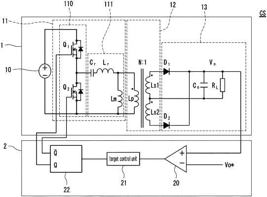
7. A controller for controlling a power converter that includes a voltage generation circuit for generating a voltage waveform containing an alternating current and a resonant circuit for converting the generated voltage waveform,
the controller comprising:
a comparator unit that compares a value relating to an output from the power converter, with a target value thereof;
a target control unit that derives a control target voltage that is a desired value for control, based on a result of a comparison by the comparator unit; and
a voltage generation circuit control unit that controls the voltage generation circuit by a control target power factor corresponding to the control target voltage derived by the target control unit, wherein
the voltage generation circuit control unit comprises:
a reference phase acquisition circuit that acquires a voltage across a resonant capacitor provided in the resonant circuit and then acquires a reference phase based on the voltage across the resonant capacitor, the reference phase serving as a reference for a phase of a current through the resonant circuit;
a waveform generation circuit that generates, from the reference phase acquired by the reference phase acquisition circuit, a time-varying waveform that changes over time;
a phase difference calculation circuit that calculates, based on a target phase difference that is a desired phase difference and also based on the time-varying waveform generated by the waveform generation circuit, a target value in the time-varying waveform as a value corresponding to the target phase difference; and
a control signal output circuit for controlling the voltage generation circuit, the control signal output circuit outputting at least one voltage generation circuit control signal for controlling the voltage generation circuit, based on the time-varying waveform generated by the waveform generation circuit and the target value calculated by the phase difference calculation circuit,
the waveform generation circuit generates a sawtooth wave as the time-varying waveform, a voltage of the sawtooth wave changing over time along a substantially uniform slope in a time period from the reference phase acquired by the reference phase acquisition circuit until a next reference phase,
the phase difference calculation circuit calculates a value of a voltage corresponding to the target phase difference as a target phase difference voltage, in the voltage of the sawtooth wave that changes over time along the substantially uniform slope,
and
the control signal output circuit for controlling the voltage generation circuit outputs the at least one voltage generation circuit control signal, based on a result of a comparison in which the voltage of the sawtooth wave generated by the waveform generation circuit is compared with the target phase difference voltage calculated by the phase difference calculation circuit.
|