| CPC H01L 29/7787 (2013.01) [H01L 29/2003 (2013.01)] | 21 Claims |

|
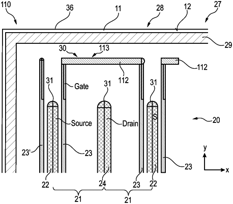
1. An enhancement mode Group III nitride-based transistor device, comprising:
a body comprising a first surface, the body further comprising a Group III nitride barrier layer arranged on a Group III nitride channel layer and forming a heterojunction therebetween capable of supporting a two-dimensional carrier gas;
a first cell field comprising plurality of transistor cells, each transistor cell comprising a source finger, a gate finger and a drain finger that extend substantially parallel to one another on the first surface and in a longitudinal direction, the gate finger being arranged laterally between the source finger and the drain finger and comprising a p-doped Group III nitride finger arranged between a metallic gate finger and the first surface;
an edge region surrounding the plurality of transistor cells and comprising an edge termination structure, wherein the edge termination structure comprises an isolation ring that locally interrupts the two-dimensional carrier gas;
a gate runner extending transversely to the longitudinal direction and comprising a plurality of separate sections that are laterally spaced apart from one another, wherein each section of the gate runner is coupled to and extends between two gate fingers which are positioned on opposing lateral sides of the drain finger; and
a power gate runner above the gate runner and extending transversely to the longitudinal direction, wherein the gate runner is electrically coupled to the power gate runner by at least one gate contact via.
|