| CPC G03B 17/561 (2013.01) [F16M 11/12 (2013.01); G03B 17/566 (2013.01)] | 18 Claims |

|
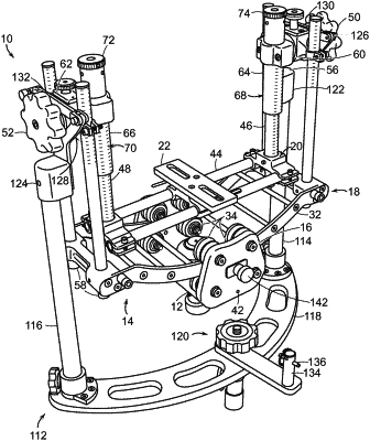
1. A camera support comprising:
a post defining a first axis, said post being disposable so that said first axis extends vertically;
a gimbal assembly; and
a first mounting member axially coupling said gimbal assembly to said post for rotation of said gimbal assembly in a horizontal plane about said first axis, said first mounting member and said gimbal assembly being secured to said post proximate to and along said first axis
wherein said gimbal assembly includes:
a first rigid body having a periphery, said first rigid body being secured along said periphery to said first mounting member for rotation in a vertical plane about a second axis perpendicular to said first axis, said periphery being disposed at a distance from said second axis;
a second rigid body movably mounted to said first rigid body for rotation in another vertical plane about a third axis perpendicular to both said first axis and said second axis, said second rigid body being secured to said first rigid body proximate to and along said third axis;
a second mounting member connected to said second rigid body for attaching a camera to said second rigid body; and
two bearing members spaced from one another along said third axis,
said second rigid body being rotatably mounted by at least one axle to said bearing members for rotation of said second rigid body about said third axis;
said first rigid body including at least two arms parallel to one another and spaced from one another in a direction parallel to said third axis;
said bearing members being adjustably fixable to respective ones of said at least two arms to vary effective lengths of said at least two arms between said periphery and said bearing members in a direction transverse to said third axis for shifting a center of gravity of said first rigid body, said second rigid body and the camera relative to said second axis, thereby enabling a placement of said center of gravity on said second axis,
wherein said at least one axle is configured for disposition on a rest of a docking stand to hold the camera support upon placement of the camera support on the docking stand, said at least one axle being configured to abuttingly engage said docking stand to prevent rotation of the second rigid body about the third axis.
|