| CPC G01R 31/52 (2020.01) [G01R 27/18 (2013.01); G01R 27/2605 (2013.01); G01R 27/26 (2013.01); G01R 31/00 (2013.01)] | 7 Claims |

|
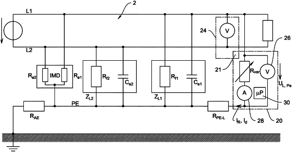
1. A method for detecting a leakage current (Id) in an ungrounded, single-phase alternating-current power supply system (2) having two outer conductors (L1, L2), the method comprising the following steps:
a) switching a variable test resistance (Rvar) between one of the outer conductors (L1, L2) and ground (PE), a test-resistance value being supposed to be set infinitely,
b) measuring an operating voltage (U0) of the alternating-current power supply system (2) between the outer conductors (L1, L2) by means of line-voltage measuring equipment (24),
c) measuring an outer-conductor-to-ground voltage (UL,Pe) between one of the outer conductors (L1, L2) and ground (PE) by means of ground-voltage measuring equipment (26),
d) should the condition that the outer-conductor-to-ground voltage (UL,Pe) be greater than or equal to half the operating voltage (U0) not be fulfilled, switching the variable test resistance (Rvar) between the other outer conductor (L1, L2) and ground (PE),
e) determining a minimally admissible test-resistance value (Rvar,min) for the variable test resistance (Rvar),
f) determining at least three support test-resistance values (Rvar,i) as support locations starting from the minimally admissible test-resistance value (Rvar,min),
g) setting the support test-resistance value (Rvar,i) and measuring a correspondingly resulting, measured test current (IR, IRi) via the variable test resistance (Rvar) by means of current measuring equipment (28) for detecting a functional metrological dependency of the measured test current (IRi) of the support test-resistance value (Rvar,i),
h) mapping the alternating-current power supply system (2) via an equivalent circuit having the test resistance (Rvar) and having leakage impedances (ZL1, ZL2) which have a capacitive portion of leakage capacitances (Ce1, Ce2) of the alternating-current power supply system (2),
i) determining the leakage capacitances (Ce1, Ce2) from an equations system, which describes the equivalent circuit, by means of a numerical approximation method such that the deviation of a calculated test current (IR,fit, IRi,fit) from the measured test current (IRi) is minimized to the support test-resistance values (Rvar,i),
j) calculating the leakage current (Id) as a calculated test current (IR,fit, IR0,fit) from the equations system having the detected leakage capacitances (Ce1, Ce2) and having the rest-resistance value (Rvar, R0) zero,
k) outputting the leakage current (Id) and the leakage capacitances (Ce1, Ce2).
|