| CPC F25D 17/065 (2013.01) [F25C 1/24 (2013.01); F25C 1/25 (2018.01); F25C 5/22 (2018.01); F25D 21/004 (2013.01); F25D 29/00 (2013.01); F25C 2400/10 (2013.01); F25D 2317/061 (2013.01); F25D 2317/063 (2013.01); F25D 2317/0681 (2013.01)] | 9 Claims |

|
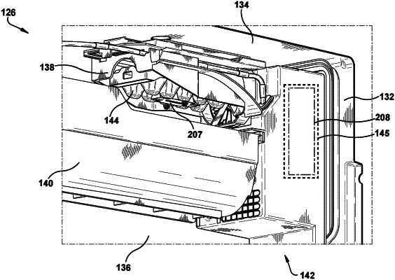
1. An ice maker for a refrigeration appliance, the ice maker comprising:
an ice maker frame extending between a first end and a second end, the ice maker frame comprising an air inlet provided at the first end of the ice maker frame;
an ice tray rotatably secured to the ice maker frame and configured to form ice pieces in the ice tray; and
an air handler comprising a housing with a front face, and
an outlet diffuser disposed at the front face and formed integrally with the front face, the outlet diffuser comprising a central body defined by a first wall, the first wall being peripherally surrounded by, and radially spaced apart from, a second wall, wherein a plurality of radially extending fins are disposed between the first wall and the second wall, wherein each of the plurality of radially extending fins is spaced apart, one from the other, along an outer peripheral surface of the first wall, and wherein the second wall of the outlet diffuser stands proud of the front face of the housing so that the second wall extends a distance forward from the front face of the air handler,
wherein in an installed position, the outlet diffuser is disposed directly adjacent the air inlet provided at the first end of the ice maker frame,
wherein the air inlet of the ice maker frame comprises a first wall that is peripherally surrounded by, and radially spaced apart from, a second wall,
wherein a projection rib radially extends between the first and second walls of the air inlet, and
wherein the second wall of the outlet diffuser is peripherally surrounded by the second wall of the air inlet such that the second wall of the outlet diffuser is received within the second wall of the air inlet, and wherein an outer, circumferential surface of the second wall of the outlet diffuser is radially spaced from an inner, circumferential surface of the second wall of the air inlet at a location where the second wall of the outlet diffuser is received within the second wall of the air inlet.
|
|
9. An ice maker for a refrigeration appliance, the ice maker comprising:
an ice maker frame having an air inlet provided at a first end of the ice maker frame, the air inlet comprising a first wall peripherally surrounded by, and radially spaced apart from, a second wall, wherein a projection rib radially extends from the first wall to the second wall of the air inlet, and wherein a cylindrical connection member is peripherally surrounded by the first wall of the air inlet;
an ice tray configured to form ice pieces in the ice tray, the ice tray comprising a first end having a pin, wherein the pin is received within the cylindrical connection member of the air inlet to rotatably secure the ice tray to the ice maker frame; and
an air handler comprising a housing with a front face, and
an outlet diffuser disposed at the front face and integrally formed with the front face, the outlet diffuser comprising a central body provided at a radial center of the outlet diffuser, the central body being defined by a first wall, the first wall being peripherally surrounded by, and radially spaced apart from, a second wall, wherein a plurality of radially extending fins are disposed between the first wall and the second wall, wherein each of the plurality of radially extending fins is spaced apart, one from the other, along an outer peripheral surface of the first wall, and wherein the second wall of the outlet diffuser stands proud of the front face of the housing so that the second wall extends a distance forward from the front face of the air handler,
wherein the first wall of the outlet diffuser and the first wall of the air inlet are both cylindrical in shape, wherein the first wall of the outlet diffuser is axially aligned with the first wall of the air inlet, and wherein the second wall of the outlet diffuser is peripherally surrounded by the second wall of the air inlet such that the second wall of the outlet diffuser is received within the second wall of the air inlet, and wherein an outer, circumferential surface of the second wall of the outlet diffuser is radially spaced from an inner, circumferential surface of the second wall of the air inlet at a location where the second wall of the outlet diffuser is received within the second wall of the air inlet,
wherein a fan is disposed within the housing, the fan including a blade having a pitch that is opposite to a pitch of each of the plurality of radially extending fins of the outlet diffuser such that, during an operating state of the fan, the fan is configured to direct an airflow out of the outlet diffuser and into the air inlet of the ice maker frame in a substantially linear direction,
wherein the second wall of the air inlet extends between first and second edges in a direction parallel to a rotational axis of the ice tray, wherein the first edge is positioned closer to the ice tray than the second edge, and wherein the projection rib is recessed from the second edge in said direction.
|