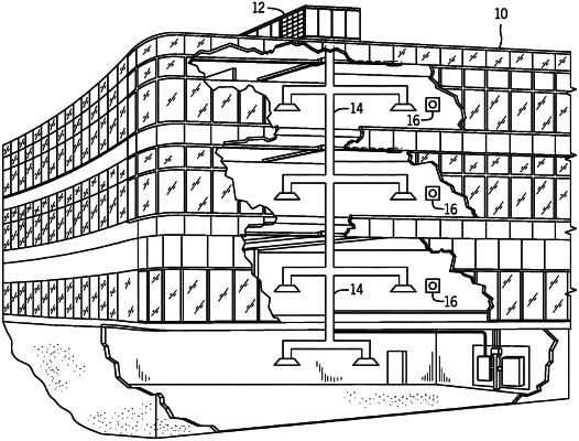
| CPC F25B 13/00 (2013.01) [F25B 30/02 (2013.01); F25B 41/31 (2021.01); F25B 2500/09 (2013.01); F25B 2600/2513 (2013.01)] | 20 Claims |

|
1. An energy efficient heat pump for a heating, ventilation, and air conditioning (HVAC) system, comprising:
a vapor compression circuit;
a heat exchanger of the vapor compression circuit configured to place a working fluid in a heat exchange relationship with an air flow directed across the heat exchanger; and
a conduit system of the vapor compression circuit configured to receive the working fluid from the heat exchanger via a first flow path of the conduit system and to direct the working fluid into the heat exchanger via a second flow path of the conduit system, wherein the conduit system comprises a third flow path extending from the first flow path to the second flow path, and wherein the conduit system is configured to direct the working fluid into the heat exchanger to place the working fluid in a counterflow arrangement with the air flow directed across the heat exchanger in a cooling mode of the heat pump and in a heating mode of the heat pump, and the first flow path of the conduit system is configured to receive the working fluid from the heat exchanger in the cooling mode of the heat pump and in the heating mode of the heat pump.
|