| CPC F16K 37/0083 (2013.01) [F04B 43/009 (2013.01); F04B 43/02 (2013.01); F16K 37/0091 (2013.01); F04B 2201/0803 (2013.01); Y10T 137/3084 (2015.04); Y10T 137/5907 (2015.04); Y10T 137/8342 (2015.04)] | 15 Claims |

|
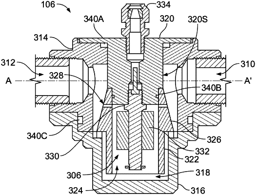
1. A diaphragm pump leak detection method comprising:
obtaining a diaphragm pump leak detection device comprising:
a body comprising:
an airflow inlet;
an airflow outlet arranged to align with the airflow inlet; and
a liquid reservoir in a bottom portion of the body;
a liquid separator positioned directly between the airflow inlet and the airflow outlet, the liquid separator dividing an airflow path from the airflow inlet to the airflow outlet into at least two separate flow paths around the liquid separator; and
a liquid level detector at least partially contained within a channel, wherein the channel is in liquid communication with the liquid reservoir,
wherein the airflow inlet, liquid separator, and airflow outlet together define the airflow path from the airflow inlet, around the liquid separator, and to the airflow outlet that does not pass through the liquid reservoir;
receiving, by the diaphragm leak detection device, exhaust air from an air-operated diaphragm pump at the airflow inlet;
removing liquid entrained in the exhaust air by using the liquid separator that is positioned directly between the airflow inlet and the airflow outlet in the airflow path to direct a flow of the exhaust air into the at least two separate flow paths around the liquid separator, wherein impingement of the exhaust air on the liquid separator removes the liquid from the exhaust air;
directing the liquid into the liquid reservoir positioned below the liquid separator;
after removing the liquid entrained in the exhaust air, directing the exhaust air to the airflow outlet that is aligned with the airflow inlet; and
providing a leak indication signal responsive to activation of the liquid level detector that is at least partially contained within a channel defined by a lower portion of the liquid separator and the channel being in liquid communication with the liquid reservoir.
|