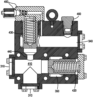
| CPC F15B 21/0423 (2019.01) [E02F 9/226 (2013.01); E02F 9/2267 (2013.01)] | 17 Claims |

|
1. A work machine, comprising:
a frame;
a traction system supporting the frame;
an implement system supported by the frame; and
a hydraulic system configured to drive movement of the implement system, the hydraulic system including a hydraulic oil tank, a control circuit, an oil cooler, and a cooler bypass valve assembly being formed as a unified valve body, the cooler bypass valve assembly being fluidly connected to the control circuit by a control circuit return line and having:
an unloading valve configured to allow hydraulic oil to flow from the control circuit return line to the hydraulic oil tank if a pressure of hydraulic oil in the control circuit return line exceeds a first threshold, the unloading valve being disposed in an unloading valve bore within the unified valve body,
a backpressure valve configured to allow hydraulic oil to flow from the return line to the oil cooler through an oil cooler inlet line if a pressure of hydraulic oil in the control circuit return line exceeds a second threshold, wherein the first threshold is greater than the second threshold, the backpressure valve being disposed in a backpressure valve bore within the unified valve body, the unloading valve bore and the backpressure valve bore being perpendicular to each other, and
an orifice configured to limit the flow of hydraulic oil through the backpressure valve.
|