| CPC F02C 7/222 (2013.01) [F02C 3/04 (2013.01); F02C 9/26 (2013.01); F23C 7/004 (2013.01); F23D 11/383 (2013.01); F23R 3/14 (2013.01); F23R 3/26 (2013.01); F23R 3/28 (2013.01); F23R 3/286 (2013.01); F23R 3/343 (2013.01); F23R 3/346 (2013.01); F02K 3/06 (2013.01); F05D 2220/32 (2013.01); F05D 2220/323 (2013.01); F23D 2202/00 (2013.01); F23D 2900/00008 (2013.01); F23D 2900/00015 (2013.01); F23D 2900/11001 (2013.01); F23R 2900/03343 (2013.01)] | 19 Claims |

|
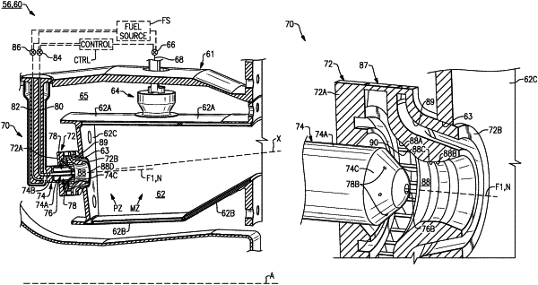
1. A combustor assembly for a gas turbine engine comprising:
a combustion chamber; and
a fuel injector assembly in communication with the combustion chamber, the fuel injector assembly comprising:
a nozzle including a nozzle body, a primary fuel injector along a nozzle longitudinal axis, and an array of secondary plain jet fuel injectors axially forward of the primary fuel injector relative to the nozzle longitudinal axis; and
a swirler body situated about the nozzle to define an injector passage that converges to a throat, the throat defined at a distance from the combustion chamber relative to the nozzle longitudinal axis;
wherein the nozzle body extends along the nozzle longitudinal axis between a first end portion and a second end portion, a periphery of nozzle body along the second end portion is established by an annular wall that tapers inwardly to a terminal end of the nozzle body, and the nozzle longitudinal axis extends through a primary outlet of the primary fuel injector along the second end portion;
wherein the injector passage includes a first passage section merging into a second passage section, the first passage section is an inward sloping annulus defined between the swirler body and the nozzle, the second passage section interconnects the first passage section and the combustion chamber, and the second passage section defines the throat;
wherein the periphery of the second end portion defines a radially inner wall of the first passage section, and the radially inner wall opposes a radially outer wall of the first passage section established by the swirler body;
wherein outlets of the secondary plain jet fuel injectors are circumferentially distributed about the annular wall along the first passage section such that the outlets are spaced apart from the terminal end of the nozzle body relative to the nozzle longitudinal axis, and each of the secondary plain jet fuel injectors defines a second fuel injector axis extending through the respective outlet such that a projection of the second fuel injector axis intersects the radially outer wall of the injector passage along the first passage section; and
wherein the radially inner wall tapers into an axial face that establishes the terminal end of the nozzle body, and the primary outlet of the primary fuel injector is established along the axial face.
|