| CPC F01D 25/16 (2013.01) [F01D 25/18 (2013.01); F02B 39/14 (2013.01); F16C 33/6637 (2013.01); F05D 2220/40 (2013.01); F05D 2240/54 (2013.01); F05D 2260/98 (2013.01)] | 5 Claims |

|
1. A turbocharger, comprising:
a rolling bearing including at least one rolling element for rotatably supporting a rotational shaft;
a bearing support cylinder located on a radially outer side relative to the rolling bearing, for supporting the rolling bearing; and
a housing located on the radially outer side relative to the bearing support cylinder, for covering a circumference of the bearing support cylinder,
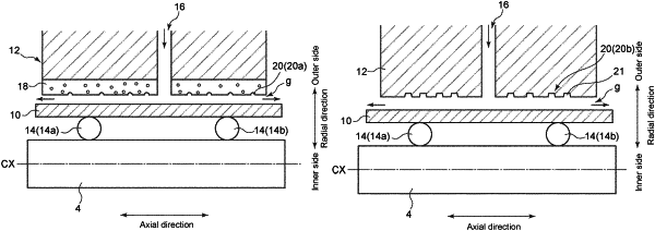
wherein, between an outer circumferential surface of the bearing support cylinder and an inner circumferential surface of the housing, a gap for forming an oil film by inflow of lubricant oil is provided,
wherein at least one of the outer circumferential surface of the bearing support cylinder and the inner circumferential surface of the housing includes an oil film holding portion for suppressing outflow of the lubricant oil from the gap, and
wherein the oil film holding portion is a protrusion disposed on the outer circumferential surface of the bearing support cylinder, or the protrusion is disposed, wherein at least a part of the housing is a porous layer, on the inner circumferential surface of the housing.
|