| CPC F01D 21/12 (2013.01) [F01D 21/00 (2013.01); F01D 25/26 (2013.01); F05D 2220/31 (2013.01); F05D 2240/14 (2013.01); F05D 2270/303 (2013.01)] | 13 Claims |

|
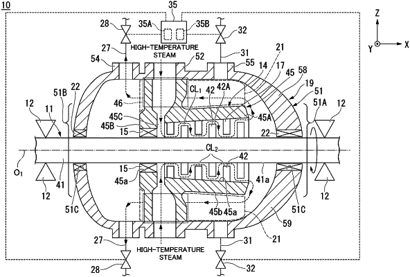
1. A steam turbine comprising:
a rotor that is configured to rotate around an axis;
an inner casing that is provided with
an inner casing main body, which accommodates the rotor and into which steam introduced thereto is discharged as exhaust steam from a first end in a direction along the axis, and
a steam inlet portion, which is provided on an outer side of the inner casing main body and through which the steam is introduced into the inner casing main body;
an outer casing that is provided with
an outer casing main body, which accommodates the inner casing and which defines a flow path that extends in the direction along the axis between the outer casing main body and an outer circumferential surface of the inner casing main body and through which the exhaust steam flows, the outer casing main body having a first end in the direction along the axis and an opposite second end in the direction along the axis,
a steam inlet port provided on the outer casing main body and configured to introduce the steam into the steam inlet portion,
a first steam outlet port, which is provided in the outer casing main body and through which the exhaust steam flowing through an entire length of the flow path in the direction along the axis is discharged to an outside, and
a second steam outlet port, which is provided in the outer casing main body and through which the exhaust steam passing through a portion of the flow path or the exhaust steam not passing through the flow path is discharged to the outside;
a first valve that adjusts opening of the first steam outlet port;
a second valve that adjusts opening of the second steam outlet port;
a first outlet line connecting the first steam outlet port and the first valve;
a second outlet line provided independently of the first outlet line and connecting the second steam outlet port and the second valve; and
a control unit that is electrically connected to the first valve and the second valve,
wherein an upstream side of the first valve is connected only to the first steam outlet port, and an upstream side of the second valve is connected only to the second steam outlet port,
wherein the second steam outlet port is arranged at a position that is closer to the second end of the outer casing main body in the direction along the axis than is a position where the steam inlet portion is arranged,
wherein the first steam outlet portion is arranged at a position that is closer to the first end of the outer casing main body in the direction along the axis than is the position where the steam inlet portion is arranged,
wherein the control unit is configured to adjust opening of the first and second valves such that an amount of exhaust steam larger than a half of the exhaust steam present in the outer casing is discharged through the first steam outlet port at a rated operation state, and
wherein an amount of exhaust steam larger than a half of the exhaust steam is discharged through the second steam outlet port in at least one of a period at which transition from the rated operation state to an operation stoppage state is performed and a period at which a transition from the operation stoppage state to the rated operation state is reached.
|