| CPC E21B 21/106 (2013.01) [F16K 31/02 (2013.01); G05D 7/0664 (2013.01)] | 3 Claims |

|
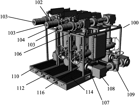
2. A modular managed pressure drilling system for a well, the system comprising:
a first skid;
a first flow control device secured to the first skid;
a first inlet flow junction providing a first port and a second port;
the first port connected to an inlet of the first flow control device, wherein the first inlet flow junction directs fluid through the first port into the first flow control device from the well;
the first inlet flow junction directing the fluid to flow in two separate paths, a first path through the first port that directs the fluid through the first flow control device and a second path that does not flow through the first flow control device;
a second skid;
a first component secured to the second skid, wherein the first inlet flow junction connects to the first component, wherein the fluid flows in the second path from the first flow junction to the first component;
wherein the first inlet flow junction provides a third path, wherein fluid flowing through the third path bypasses the first flow control device and the first component;
a third skid attachable to the first and second skid;
a pressure relief valve attached to the third skid;
wherein the third path bypasses the pressure relief valve;
the first inlet flow junction provides a fourth path, wherein fluid flowing through the fourth path flows to the pressure relief valve.
|