| CPC E05D 3/12 (2013.01) [E05D 3/06 (2013.01); E05D 5/06 (2013.01); E05D 7/0018 (2013.01); E05Y 2600/10 (2013.01); E05Y 2600/622 (2013.01)] | 18 Claims |

|
1. A hinge assembly with reinforced abutments, comprising:
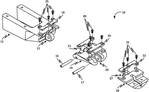
an upper hinge member, a lower hinge member, and a middle hinge member hingedly coupled between said upper hinge member and said lower hinge member via a first connecting pin linking the upper hinge member to the middle hinge member and a second connecting pin linking the lower hinge member to the middle hinge member such that said hinge assembly is configured to be positioned into a straightened state and a folded state;
the upper hinge member having a first strike plate and at least one connecting pin bore dimensioned to receive said first connecting pin;
the lower hinge member having a second strike plate and at least one connecting pin bore dimensioned to receive said second connecting pin;
the middle hinge member having a third strike plate, a fourth strike plate, at least one connecting bore dimensioned to receive said first connecting pin, and at least one connecting bore dimensioned to receive said second connecting pin;
a first abutment joint formed between an abutment surface of said first strike plate of said upper hinge member and an abutment surface of said third strike plate of said middle hinge member when said upper hinge member and said middle hinge member are in said straightened state; and
a second abutment joint formed between an abutment surface of said second strike plate of said lower hinge member and an abutment surface of said fourth strike plate of said middle hinge member when said lower hinge member and said middle hinge member are in said straightened state;
wherein said first abutment joint is configured to be selectively opened by rotating said upper hinge member relative to said middle hinge member and said second abutment joint is configured to be selectively opened by rotating said lower hinge member relative to said middle hinge member when said upper hinge member, said lower hinge member, and said middle hinge member are positioned into said folded state; and
wherein said middle hinge member further comprises a third recess, said third strike plate is dimensioned to fit within said third recess of said middle hinge member, said third recess having a perimeter and shape that approximates at least a portion of said third strike plate.
|