| CPC E05B 47/0012 (2013.01) [E05B 47/026 (2013.01); E05B 55/005 (2013.01); E05B 63/0056 (2013.01); E05B 63/08 (2013.01)] | 5 Claims |

|
1. A door bolt lock structure comprising:
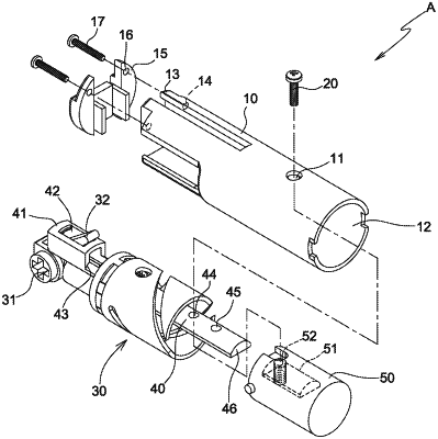
a casing, a cavity defined in the casing, and a locking orifice formed on a predetermined position of a first end of the casing;
a drive element accommodated in the cavity of the casing, the drive element including a lock cylinder mounted on an end of the drive element, and the drive element including a control lever extending from a side of the lock cylinder;
a slide plate slidably received in the drive element and including a holder formed on a first end of the slide plate, a groove defined in the holder so that the control lever of the drive element slides in the groove, a free segment extending from a second end of the slide plate, a first locating orifice defined on a side of the free segment adjacent to the defining portion, and a second locating orifice defined on the side of the free segment away from the defining portion; and
a head including a trench configured to receive the free segment of the slide plate, a threaded orifice defined on a top of the head and communicating with the trench, wherein the threaded orifice is selectively aligned with the first locating orifice or the second locating orifice of the slide plate, and a second screw element is inserted through the locking orifice of the casing, the first locating orifice or the second locating orifice, and the threaded orifice of the head so as to adjustably move the head with respect to the slide plate.
|