| CPC B65G 47/5131 (2013.01) [B65G 47/5122 (2013.01)] | 15 Claims |

|
1. A buffer conveyor, comprising:
an input station and an output station,
a drivable endless conveyor belt which successively follows a transport path from the input station to the output station and a return path from the output station to the input station, wherein the lengths of the transport path and the return path are inversely adjustable, and
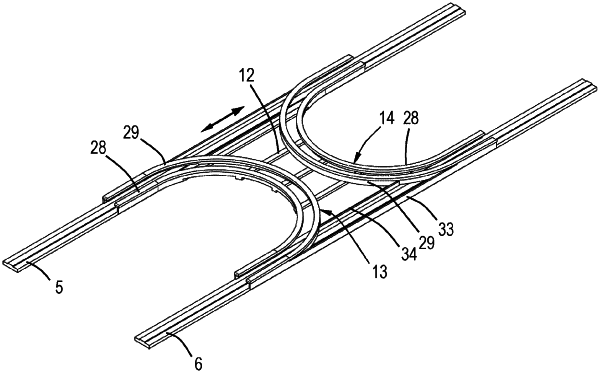
a frame, wherein at the transport path the frame is provided with two parallel transport path frame legs for guiding the conveyor belt along the transport path frame legs and a U-shaped transport path bridge for guiding the conveyor belt between the transport path frame legs, wherein the transport path bridge includes a curved bridge portion and parallel bridge legs extending from the curved bridge portion, which transport path bridge is at least partly located between the transport path frame legs and displaceable along the transport path frame legs, wherein within the transport path the conveyor belt successively follows from the input station one of the transport path frame legs, one of the bridge legs, the curved bridge portion, the other one of the bridge legs and the other one of the transport path frame legs to the output station, wherein each of the transport path frame legs is provided with a transport path frame guide for supporting a lateral contact side of the conveyor belt in outward direction as seen from the other transport path frame leg, wherein the transport path bridge is shaped such that along the curved bridge portion and respective twisted regions of the bridge legs adjacent to the curved bridge portion the conveyor belt has a transverse down-slope towards the inside of the U-shape and such that the lateral contact side of the conveyor belt at said twisted regions is above the respective transport path frame guides.
|