| CPC B64G 1/506 (2013.01) [F28D 1/0246 (2013.01); F28D 15/0233 (2013.01); F28F 1/022 (2013.01); F28F 1/06 (2013.01); F28F 1/40 (2013.01); F28F 9/0282 (2013.01); F28D 2021/0064 (2013.01); F28D 2021/0071 (2013.01)] | 20 Claims |
|
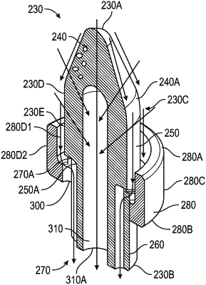
1. An insert for a parallel passage condensing heat exchanger, the insert comprising:
a forward end, an aft end, and a body extending aft from the forward end to the aft end, the body defining:
a body exterior surface;
a forward segment that extends aft from the forward end of the insert to a first axial location between the forward and aft ends of the insert, wherein along the forward segment the body exterior surface is without openings and has a frustoconical shape;
a middle segment that extends aft from the first axial location to a second axial location that is forward of the aft end of the insert, wherein along the middle segment the body exterior surface is cylindrical; and
an aft segment that extends aft from the second axial location to the aft end of the insert, wherein along the aft segment the body exterior surface of the body is cylindrical and defines axially extending grooves, and wherein the grooves are circumferentially spaced apart from each other and extend forward from the aft end of the insert to the middle segment to define a forward end of the grooves.
|