| CPC B60W 60/0015 (2020.02) [B60W 40/10 (2013.01); B60W 2420/42 (2013.01); B60W 2422/10 (2013.01)] | 20 Claims |

|
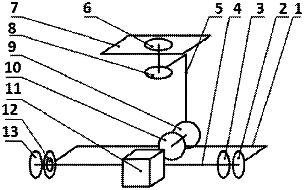
1. A vehicle-mounted camera gimbal servo system, comprising a camera tri-axial gimbal and a servo control apparatus, wherein
the camera tri-axial gimbal comprises:
(a) a pitch motor comprising a pitch motor stator (2), a pitch motor rotor (3), and one or more pitch position sensors disposed inside the pitch motor;
(b) a yaw motor comprising a yaw motor stator (6), a yaw motor rotor (8), and one or more yaw position sensors disposed inside the yaw motor;
(c) a roll motor comprising a roll motor stator (9), a roll motor rotor (10), and one or more roll position sensors disposed inside the roll motor;
(d) a roll arm (1);
(e) a pitch arm (4);
(f) a yaw arm (5);
(g) a camera (11) fixedly connected to the pitch motor rotor (3) through the pitch arm (4), and the pitch motor rotor (3) configured to cause movement of the camera (11) in a pitch direction;
(h) a counterweight block (13) connected to the pitch arm (4) in a threaded manner, the counterweight block (13) configured to compensate for a gravitational unbalance moment in a roll direction caused by a self-weight of the pitch motor;
(i) a pitch-axis bearing (12) configured to constrain the pitch arm (4);
(j) a gimbal top (7) fixed at a fixing position on a first side of an inner rear-view mirror mounted on an inner top portion of a vehicle, wherein all components of the camera tri-axial gimbal are fixedly connected to the inner top portion of the vehicle via the inner rear-view mirror;
wherein the pitch motor stator (2) is fixedly connected to the roll motor rotor (10) through the roll arm (1), the roll motor rotor (10) configured to cause movement of the camera (11) in the roll direction;
wherein the roll motor stator (9) is fixedly connected to the yaw motor rotor (8) through the yaw arm (5), the yaw motor rotor (8) configured to cause movement of the camera (11) in a yaw direction;
wherein the yaw motor stator (6) is fixedly connected to the gimbal top (7); and
the servo control apparatus comprises:
(k) an inertial measurement unit, mounted on the camera (11), the inertial measurement unit configured to measure angular velocity information and angular displacement information of the camera (11), and the inertial measurement unit comprising quaternion complementary filtering algorithm configured to generate precise angular velocity information based on the angular velocity information of the camera (11) and precise angular displacement information based on the angular velocity information of the camera (11);
(l) an actuator control unit comprising a drive bridge, the actuator control unit configured to generate insulated-gate bipolar transistor (IGBT) switching sequence information and an IGBT duty cycle of the drive bridge in three directions according to the one or more pitch position sensors in the pitch motor, the one or more yaw position sensors in the yaw motor, the one or more roll position sensors in the roll motor, and target voltage information, and the actuator control unit further configured to implement open-loop control in the three directions by using the drive bridge to selectively control speeds of each of the pitch motor, the yaw motor, and the roll motor;
(m) an angular velocity loop control unit comprising a first particle swarm algorithm configured to perform a first parameter optimization and an angular velocity loop controller model, the angular velocity loop control unit configured to establish the angular velocity loop controller model after the first parameter optimization and to obtain the target voltage information according to a combination of the angular velocity information obtained by the inertial measurement unit and target angular velocity information, and the angular velocity loop control unit further configured to sends the target voltage information to the actuator control unit; and
(n) an angular displacement loop control unit comprising a second particle swarm algorithm configured to perform a second parameter optimization and an angular displacement loop controller model, the angular displacement loop control unit configured to establish the angular displacement loop controller model after the second parameter optimization and to obtain the target angular velocity information according to target steering information set by a user and the angular displacement information obtained by the inertial measurement unit, and the angular displacement loop control unit further configured to send the target angular velocity information to the angular velocity loop control unit to implement double closed-loop control.
|