| CPC B60R 9/04 (2013.01) [B60R 13/06 (2013.01); B62D 27/02 (2013.01)] | 19 Claims |

|
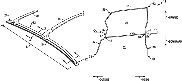
1. A motor vehicle assembly, comprising:
a roof rail including a closed cross-sectional area and an open cross-sectional area separated by a divider wall,
wherein the roof rail includes a first side wall having a first end and a second end, a second side wall having a first end and a second end, and a cap wall extending between the second end of the first side wall and the second end of the second side wall,
wherein the first side wall includes a first groove recessed toward the second side wall in a horizontal direction relative to adjacent surfaces of the first side wall both vertically above and vertically beneath the first groove,
wherein the second side wall includes a second groove recessed toward the first side wall in a horizontal direction relative to adjacent surfaces of the second side wall both vertically above and vertically beneath the second groove,
wherein the divider wall extends between the first side wall and the second side wall,
wherein the divider wall projects from the first side wall at a first location vertically aligned with the first groove,
wherein the divider wall projects from the second side wall at a second location vertically aligned with the second groove,
wherein the first groove is partially defined by a substantially planar segment of the first side wall,
wherein the second groove is partially defined by a substantially planar segment of the second side wall,
wherein the first location is on the substantially planar segment of the first side wall,
wherein the second location is on the substantially planar segment of the second side wall,
wherein the substantially planar segment of the first side wall lies in a first plane, and the substantially planar segment of the second side wall lies in a second plane non-parallel to the first plane,
wherein the first side wall includes an upper segment vertically above the substantially planar segment of the first side wall and spaced-apart from the first plane in a horizontal direction away from the second side wall,
wherein the first side wall includes a lower segment vertically below the substantially planar segment of the first side wall and spaced-apart from the first plane in a horizontal direction away from the second side wall,
wherein the second side wall includes an upper segment vertically above the substantially planar segment of the second side wall and spaced-apart from the second plane in a horizontal direction away from the first side wall, and
wherein the second side wall includes a lower segment vertically below the substantially planar segment of the second side wall and spaced-apart from the second plane in a horizontal direction away from the first side wall.
|