| CPC B41J 2/17509 (2013.01) [B41J 2/1754 (2013.01); B41J 2/17533 (2013.01); B41J 2/17546 (2013.01); B41J 2/17596 (2013.01)] | 7 Claims |

|
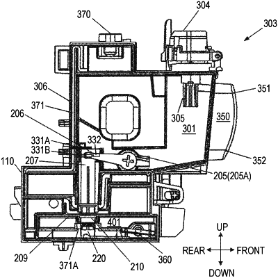
1. An ink tank configured to supply liquid to an apparatus having a liquid consumption device, the ink tank comprising:
a first liquid storage chamber storing liquid to be supplied to the liquid consumption device;
a second liquid storage chamber communicating with the first liquid storage chamber through a communication passage, the second liquid storage having a liquid outlet for supplying liquid to the liquid consumption device;
a detector having at least two electrode rods in the first liquid storage chamber, the electrode rods being disposed above the communication passage;
an injector having an opening supplying liquid to the first liquid storage chamber;
an atmospheric communication passage communicating an outside of the ink tank with the second liquid storage chamber;
a cap movable between an open position and a closed position with respect to the injector, the cap being configured to seal the first liquid storage chamber in a case the cap is in the closed position;
a valve mechanism having a flat plate portion and configured to open or close the communication passage by moving up and down with respect to the communication passage;
a link mechanism configured to move the valve mechanism up and down;
a guide portion configured to guide the valve mechanism which is moved up and down by the link mechanism, the guide portion extending from the flat plate portion of the valve mechanism in a direction orthogonal to the flat plate portion and in a vertical direction; and
a rib protruding from an inner surface of the first ink chamber and configured to guide the guide portion, the rib extending in the extending direction of the guide portion,
wherein at least a part of the guide portion is provided in the valve mechanism.
|