| CPC B05B 7/2416 (2013.01) [B05B 1/30 (2013.01); B05B 7/10 (2013.01); B05B 7/12 (2013.01)] | 6 Claims |

|
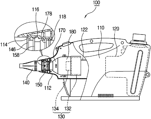
1. A liquid chemical sprayer, comprising:
in a sprayer provided with a liquid chemical container at one side of the rear while a neck having a reduced cross-sectional area is formed at the front of a main body toward the front and configured to spray liquid chemical in a chemical container by inducing an air pressure difference in an inner side of the neck by the air applied from an air blowing module composed of an electric motor and an air blowing fan,
a nozzle cap having a cylindrical structure, in which an internal cross-sectional area is reduced as toward the front and a minimum diameter portion is formed at an inner side of the front, and in which a female screw part is formed at a predetermined portion having a same inner diameter, and assembled to an annular rotation guide formed at the neck to form an annular protrusion at an outer side of a rear end portion capable of being in-place rotation with respect to the neck;
a nozzle head, in which a male screw part corresponding to the female screw part formed at the nozzle cap is formed, a nozzle is formed at a front end of a nozzle pipe formed extending a predetermined length toward the front, and a guide plate is formed protruding to be assembled to a guide rail formed at the neck capable of operating forward and backward with respect to the neck;
a valve body formed in a cylindrical shape, in which a liquid chemical supply hose is connected to a rear end and a check valve is installed therein, in which a plunger for selectively opening and closing the nozzle pipe is formed protruding in the front thereof;
a valve housing formed in a cylindrical structure fixedly installed at a rear of the nozzle head and forming a valve seat at an inner portion in which the valve body is stably installed; and
a motor housing faced and assembled with the rear of the valve housing so that the rear thereof is maintained in a fixed state, in which the air blowing module is installed,
wherein a flange surrounding a predetermined portion in the front of the motor housing is formed at a predetermined portion at the rear of the valve housing and an engaging hole corresponding to a locker protruding from the motor housing is formed in the flange.
|