| CPC A61F 2/1678 (2013.01) | 20 Claims |

|
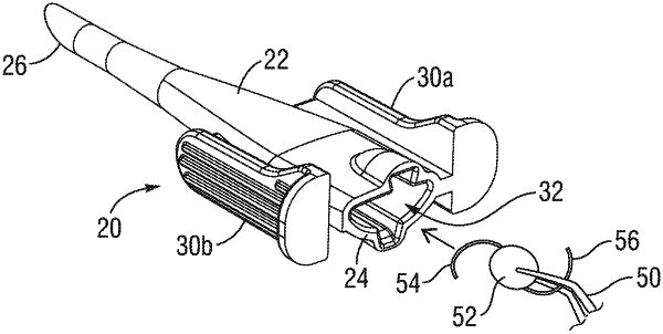
1. A cartridge for receiving and delivering an intraocular lens to the inner eye, the intraocular lens having an optic with a diameter, comprising:
a main body extending longitudinally along a longitudinal axis from a proximal opening sized to receive the optic of the intraocular lens to a tubular distal end, the main body being formed of a material selected from the group consisting of polypropylene, polycarbonate and polyurethane, and the main body having a lumen extending from the proximal opening to the distal end which defines a distal opening that is smaller than the proximal opening and smaller than the optic diameter such that passage of the IOL through the lumen causes the optic to fold into a rolled configuration, and wherein the distal end is beveled as seen in side view with a leading tip below and opposite a trailing heel, wherein between the leading tip and trailing heel the beveled distal end defines a bevel angle β as measured from a plane perpendicular to the longitudinal axis that forms a bevel plane, the distal end further defining a distal face between an exterior surface and the lumen with the distal face thus having an outer edge and an inner edge, wherein at least a portion of the distal face around the distal end is flush with the beveled distal end in the bevel plane as seen in side view, and the beveled distal end includes a chamfer that is not in the bevel plane.
|